
Mastering the Arduino Nano I2C Pins for Compact Prototyping
For compact breadboard prototyping, the Arduino Nano V3.0 remains the industry-standard form factor. Its DIP-30 footprint bridges the gap between the bulky Uno and the surface-mount Pro Mini. However, correctly configuring the Arduino Nano I2C pins requires navigating logic-level mismatches, bus capacitance limits, and address conflicts. Unlike SPI, which requires complex chip-select routing, the Inter-Integrated Circuit (I2C) bus allows you to daisy-chain dozens of sensors and displays using just two wires. In this setup and first-project tutorial, we will map the exact pinout, address the critical 5V vs. 3.3V logic hazards, and build a functional SSD1306 OLED display interface from scratch.
Pinout Breakdown: Locating the I2C Pins
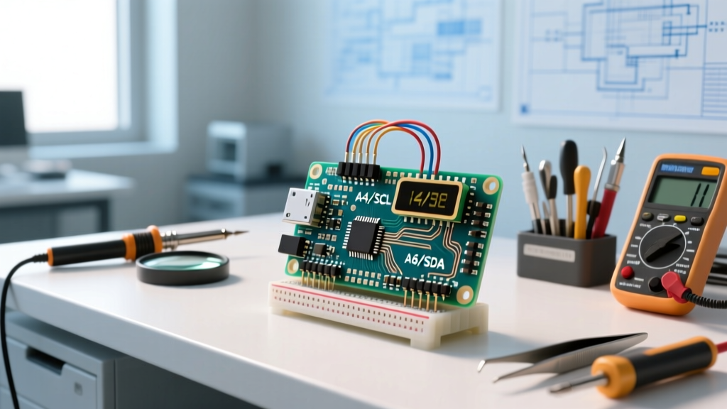
On the classic Arduino Nano (ATmega328P), the I2C pins are multiplexed with the analog inputs. They are located at the bottom right of the board when the USB port is facing up:
- A4 (SDA): Serial Data Line. This bidirectional pin handles the actual data payload.
- A5 (SCL): Serial Clock Line. This pin carries the clock signal generated by the master (the Nano) to synchronize data transfer.
⚠️ Critical Hardware Variant Warning: If you are using the newer Arduino Nano 33 IoT or Nano RP2040 Connect, the operating logic is 3.3V. Connecting a standard 5V I2C module directly to these boards without a logic level shifter will permanently damage the SAMD21 or RP2040 silicon. The classic Nano V3.0 (and most $4 clones) operates at 5V logic.
The Pull-Up Resistor Requirement
I2C uses an open-drain architecture. This means the Nano can pull the SDA and SCL lines to GND (logic 0), but it cannot actively drive them HIGH (logic 1). External pull-up resistors are mandatory to pull the lines back to VCC. While the ATmega328P has internal pull-ups, they are roughly 20kΩ to 50kΩ—too weak for reliable high-speed I2C communication. Most commercial I2C modules (like the SSD1306 OLED) include 4.7kΩ or 10kΩ surface-mount pull-up resistors on their breakout boards. If you are wiring raw I2C chips, you must add external 4.7kΩ resistors between VCC and both SDA/SCL lines.
Hardware Checklist & 2026 Market Costs
Building your first I2C project requires minimal investment. Below is a realistic Bill of Materials (BOM) based on current electronics market pricing.
| Component | Specification / Model | Est. Cost (USD) | Notes |
|---|---|---|---|
| Microcontroller | Arduino Nano V3.0 Clone (CH340G) | $4.50 | Requires CH340 USB driver for Windows/Mac |
| Display Module | SSD1306 0.96" OLED (128x64, I2C) | $3.80 | Ensure it has 4 pins (GND, VCC, SCL, SDA) |
| Logic Shifter | Bi-Directional Level Converter (BSS138) | $1.20 | Only needed if mixing 5V Nano with 3.3V sensors |
| Wiring | 22 AWG Solid Core Breadboard Jumper Kit | $6.00 | Keep I2C runs under 30cm for standard mode |
Step-by-Step Wiring Guide
Follow these exact connections to wire the SSD1306 OLED to your Nano. Keep the wires as short and parallel as possible to minimize cross-talk and parasitic capacitance.
- Ground (GND): Connect the Nano GND pin to the OLED GND pin. Establish a common ground rail on your breadboard.
- Power (VCC): Connect the Nano 5V pin to the OLED VCC pin. (Most SSD1306 modules have an onboard voltage regulator and accept 3.3V to 5V).
- Clock (SCL): Connect Nano pin A5 to the OLED SCL pin.
- Data (SDA): Connect Nano pin A4 to the OLED SDA pin.
First Project: I2C Address Scanner & OLED Setup
Before uploading complex graphics code, you must verify that the Nano can see the OLED on the I2C bus. Many cheap OLED modules ship with an I2C address of 0x3C, while others use 0x3D. According to the official Arduino Wire Library Reference, the Wire library handles the low-level I2C protocol, but it requires the exact hex address to initialize communication.
Step 1: Run the I2C Scanner
Upload this lightweight scanner sketch to your Nano. Open the Serial Monitor at 9600 baud. If wired correctly, it will output the hex address of your display.
#include <Wire.h>

void setup() {
  Wire.begin();
  Serial.begin(9600);
  while (!Serial); // Wait for serial monitor
  Serial.println("\nI2C Scanner");
}

void loop() {
  byte error, address;
  int nDevices = 0;
  for(address = 1; address < 127; address++ ) {
    Wire.beginTransmission(address);
    error = Wire.endTransmission();
    if (error == 0) {
      Serial.print("I2C device found at address 0x");
      if (address < 16) Serial.print("0");
      Serial.print(address, HEX);
      Serial.println(" !");
      nDevices++;
    }
  }
  if (nDevices == 0) Serial.println("No I2C devices found\n");
  delay(5000); // Wait 5 seconds for next scan
}
Step 2: Driving the OLED Display
Once you have confirmed the address (let's assume 0x3C), install the Adafruit SSD1306 and Adafruit GFX libraries via the Arduino Library Manager. The following code initializes the display and renders a basic diagnostic readout.
#include <Wire.h>
#include <Adafruit_GFX.h>
#include <Adafruit_SSD1306.h>

#define SCREEN_WIDTH 128
#define SCREEN_HEIGHT 64
#define OLED_RESET -1 // Reset pin not used
#define SCREEN_ADDRESS 0x3C // Change to 0x3D if scanner found that

Adafruit_SSD1306 display(SCREEN_WIDTH, SCREEN_HEIGHT, &Wire, OLED_RESET);

void setup() {
  Serial.begin(9600);
  if(!display.begin(SSD1306_SWITCHCAPVCC, SCREEN_ADDRESS)) {
    Serial.println(F("SSD1306 allocation failed"));
    for(;;); // Halt execution
  }
  display.clearDisplay();
  display.setTextSize(2);
  display.setTextColor(SSD1306_WHITE);
  display.setCursor(0, 10);
  display.println(F("I2C OK"));
  display.setTextSize(1);
  display.setCursor(0, 40);
  display.println(F("ElectricalFlux"));
  display.display();
}

void loop() {
  // Static display for this tutorial
}
Advanced Troubleshooting: Bus Capacitance and Signal Integrity
If your OLED flickers, drops out, or fails to initialize, the issue is rarely the code. It is almost always a physical layer violation. The NXP I2C Bus Specification (UM10204) strictly defines the electrical characteristics of the I2C bus. For Standard-mode (100 kHz), the maximum allowed bus capacitance is 400 pF.
Where Does Capacitance Come From?
- Microcontroller Pins: ~10 pF each.
- Breadboard Contacts: ~2 pF to 5 pF per row.
- Jumper Wires: ~15 pF per 10cm of wire.
- Module PCBs: ~15 pF per connected sensor.
If you connect three I2C sensors and an OLED using long, tangled jumper wires on a cheap breadboard, you will easily exceed the 400 pF limit. The RC time constant formed by your 4.7kΩ pull-up resistors and the 400+ pF capacitance prevents the voltage from rising fast enough to register as a logic HIGH before the next clock cycle.
The Fix: Lowering Pull-Up Resistance
If you must run a high-capacitance bus, you need stronger pull-up resistors to charge the parasitic capacitance faster. You can calculate the minimum allowable resistor value using the formula: R_min = (Vcc - Vol) / Iol. Assuming a 5V bus, a maximum voltage drop (Vol) of 0.4V, and a standard 3mA sink current (Iol), the absolute minimum resistance is roughly 1,533 Ω. Swapping your 4.7kΩ resistors for 2.2kΩ resistors will significantly sharpen the rise times on a loaded bus without exceeding the 3mA sink limit of the ATmega328P.
Next Steps and Expansion
Once your SSD1306 is rendering text, you can expand your I2C bus by adding environmental sensors like the BME280 (Address 0x76 or 0x77) or an MPU6050 accelerometer (Address 0x68). For comprehensive wiring diagrams and module-specific initialization routines, refer to the Adafruit Monochrome OLED Breakouts guide. Always remember to run an I2C scanner sketch whenever you add a new module to the bus to preemptively catch address collisions before they cause silent data corruption in your main application loop.