
Understanding the Magic of PWM on the Arduino Nano
If you are stepping into the world of microcontrollers, the Arduino Nano is arguably the best breadboard-friendly platform to start with. As of 2026, genuine Arduino Nanos retail around $24, while third-party ATmega328P clones equipped with the CH340 USB-to-serial chip can be sourced for $4 to $6 on major electronics marketplaces. Regardless of which version you own, mastering Arduino Nano PWM pins is a critical milestone for any beginner.
PWM stands for Pulse Width Modulation. Because the Nano is a digital device, its pins can only output 5 Volts (HIGH) or 0 Volts (LOW). They cannot natively output 2.5V or 3.3V. PWM solves this by rapidly toggling the pin between HIGH and LOW. By changing the ratio of ON time to OFF time (the duty cycle), you can simulate an analog voltage. This is how you fade LEDs, control motor speeds, and generate basic audio tones.
Beginner Warning: Never attempt to power a motor or high-draw component directly from a Nano PWM pin. The ATmega328P microcontroller has an absolute maximum current rating of 40mA per I/O pin, and a 200mA total limit for the entire chip. Exceeding this will permanently destroy the silicon trace inside the IC.Locating the Arduino Nano PWM Pins
Looking at your Nano's silkscreen, you will notice that several digital pins have a small tilde symbol (~) printed next to them. This tilde is the universal indicator for hardware PWM capability on Arduino boards.
The classic Arduino Nano (ATmega328P) features exactly six PWM-capable pins:
- ~D3 (Digital Pin 3)
- ~D5 (Digital Pin 5)
- ~D6 (Digital Pin 6)
- ~D9 (Digital Pin 9)
- ~D10 (Digital Pin 10)
- ~D11 (Digital Pin 11)
To utilize these pins in your code, you must use the analogWrite(pin, value) function, where the value ranges from 0 (0% duty cycle / 0V) to 255 (100% duty cycle / 5V). For a comprehensive breakdown of the underlying syntax, refer to the official Arduino analogWrite() documentation.
The 490Hz vs 980Hz Frequency Quirk (Crucial E-E-A-T Insight)
Most beginner tutorials treat all PWM pins as identical. They are not. The ATmega328P generates PWM signals using internal hardware timers, and these timers run at different default frequencies.
| PWM Pin | Hardware Timer | Default Frequency | Best Use Case |
|---|---|---|---|
| D5, D6 | Timer 0 | ~980 Hz | Motor control (reduces audible whine) |
| D3, D9, D10, D11 | Timers 1 & 2 | ~490 Hz | LED fading, general-purpose PWM |
Why does this matter? If you use a 490 Hz PWM signal to drive a small DC motor or a piezo buzzer, the rapid switching can create an annoying, high-pitched acoustic whine. By moving your motor control wire to Pin D5 or D6, you double the switching frequency to 980 Hz. This pushes the acoustic noise higher, often out of the most irritating range of human hearing, resulting in a much smoother-sounding project.
Step-by-Step Project 1: The Classic Fading LED
Let us start with a safe, low-current project to verify your PWM pins are working.
Required Components
- 1x 5mm LED (Any color)
- 1x 220Ω or 330Ω Resistor
- 2x Jumper Wires
Wiring the Circuit
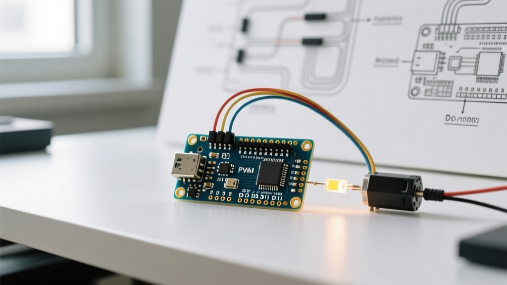
- Connect the anode (long leg) of the LED to Pin ~D9 through the 220Ω resistor.
- Connect the cathode (short leg) of the LED directly to any GND pin on the Nano.
The Code Logic
In your Arduino IDE loop, use a for loop to increment a variable from 0 to 255, passing it to analogWrite(9, fadeValue). Add a delay(15) to slow down the fade so the human eye can perceive it. Reverse the loop from 255 down to 0 to complete the breathing effect.
Step-by-Step Project 2: Safe DC Motor Speed Control
Controlling a motor requires an external power source and a switching component. Do not use the IRF520 MOSFET modules commonly found in cheap beginner kits. The IRF520 is a standard MOSFET requiring 10V at the Gate to fully open. At the Nano's 5V logic level, it operates in its linear region, causing severe voltage drops and dangerous overheating.
Instead, use a true Logic-Level MOSFET like the IRLZ44N or FQP30N06L (notice the 'L' in the part number, which denotes logic-level). These fully saturate at Vgs = 4.5V.
Required Components
- 1x IRLZ44N Logic-Level MOSFET (Approx. $1.50)
- 1x 1N4007 Flyback Diode (Approx. $0.10)
- 1x 10kΩ Pull-down Resistor
- 1x 130-size DC Motor (3V - 6V)
- External 5V or 6V Battery Pack
Wiring the Motor Circuit
- Gate (G): Connect to Nano Pin ~D5 (using 980Hz for less noise). Also, connect a 10kΩ resistor between the Gate and GND to prevent the motor from spinning erratically while the Nano boots up.
- Source (S): Connect directly to the Nano GND AND the negative terminal of your external battery pack. Sharing a common ground is mandatory.
- Drain (D): Connect to the negative wire of your DC motor.
- Motor Positive: Connect to the positive terminal of your external battery pack.
- Flyback Diode: Place the 1N4007 diode across the motor terminals, with the silver stripe (cathode) pointing toward the positive voltage. This protects the MOSFET from voltage spikes when the motor spins down.
For more detailed schematics on driving inductive loads safely, consult the SparkFun Motors and Motor Drivers tutorial.
Common Beginner Mistakes and Troubleshooting
- Using analogWrite() on Non-PWM Pins: If you write
analogWrite(4, 128)on Pin D4 (which lacks the ~ symbol), the Nano will simply output HIGH (5V) because the value is greater than 127. It will not output 2.5V. - Forgetting the Common Ground: When using external power supplies for motors or high-power LEDs, the GND of the Nano must be physically wired to the GND of the external power supply. Without this reference, the PWM signal will float and fail to trigger your MOSFET.
- Timer 0 Conflicts: Timer 0 handles Pins 5 and 6, but it also handles the
millis()anddelay()functions. If you use third-party libraries to change the PWM frequency of Pins 5/6, you will break all time-based functions in your sketch.
Frequently Asked Questions (FAQ)
Can I change the default PWM frequency?
Yes. You can alter the prescaler bits in the ATmega328P hardware registers to change the frequency. However, doing this manually is complex for beginners. It is highly recommended to use the TimerOne or PWM libraries available in the Arduino IDE Library Manager to safely adjust frequencies without breaking core Arduino functions.
Does the Arduino Nano Every have the same PWM pins?
No. The Arduino Nano Every uses the ATmega4809 chip. While it is a more powerful and modern board, its pinout and timer architectures differ. Always check the specific silkscreen for the '~' symbol on the Every, as hardware compatibility with classic Nano shields and code is not always 1:1.
What is the maximum voltage a PWM pin can output?
The HIGH state of a PWM pin is tied to the Nano's logic level, which is exactly 5V when powered via USB or the 5V pin. If you power the Nano via the RAW/VIN pin with 7-12V, the onboard regulator steps it down to 5V for the microcontroller. The PWM output will never exceed 5V.