
The ATmega328P "Analog" Misconception
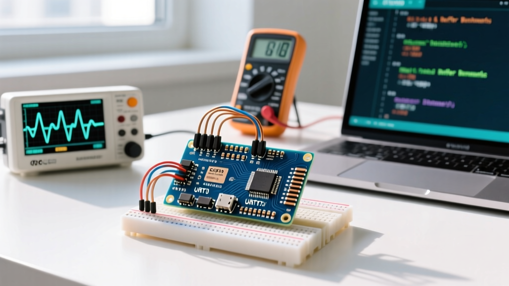
If you have ever tried to generate a true analog voltage signal using the analogWrite() function on an Arduino Nano, you have likely encountered a harsh reality: the ATmega328P microcontroller does not possess a hardware Digital-to-Analog Converter (DAC). When you call analogWrite(pin, value), the board is not outputting a steady DC voltage. Instead, it is generating a Pulse Width Modulation (PWM) square wave, typically at 490 Hz or 980 Hz, which simulates an analog average only to slow-reacting components like the human eye (via LEDs) or high-inertia DC motors.
Core Hardware Limitation: To achieve a genuine, steady-state analog voltage for applications like audio synthesis, precision motor control, or programmable power supplies, you must convert the Nano's digital or PWM signals into true analog outputs. This requires either passive filtering (Budget) or dedicated external DAC silicon (Premium).
In this guide, we break down the engineering trade-offs between building budget-friendly RC low-pass filters and integrating premium I2C DAC modules to achieve true analog outputs on Arduino Nano in 2026.
The Budget Route: PWM RC Filters & Op-Amp Buffering
The most cost-effective way to extract a DC voltage from the Nano's PWM pins (D3, D5, D6, D9, D10, D11) is by using a passive Resistor-Capacitor (RC) low-pass filter. This circuit smooths the 5V square wave into a proportional DC voltage. A basic filter costs less than $0.10 in passive components.
Calculating the Cutoff Frequency
To smooth a 490 Hz PWM signal, your filter's cutoff frequency ($f_c$) must be significantly lower than the PWM frequency to eliminate ripple. A standard starting point is a 10kΩ resistor and a 0.1µF ceramic capacitor.
- Formula: $f_c = \frac{1}{2 \pi R C}$
- Result: $\frac{1}{2 \pi (10,000)(0.0000001)} \approx 159 \text{ Hz}$
At 159 Hz, the 490 Hz PWM carrier is heavily attenuated, yielding a relatively clean DC voltage. However, the trade-off is settling time. If you rapidly change the PWM duty cycle, the capacitor takes time to charge/discharge through the 10kΩ resistor, resulting in a sluggish response (roughly 3ms to reach 63% of the target voltage).
The LM358 Buffer (Crucial Step)
A critical failure mode for budget RC filters is impedance loading. If you connect a load with an impedance lower than ~100kΩ (such as a motor driver or an ADC input on another board) directly to the RC filter, the load will act as a parallel resistor, dragging your carefully calculated voltage down and introducing massive ripple.
The Fix: Buffer the output using an LM358 dual operational amplifier (costing ~$0.50). Configure one half of the LM358 as a unity-gain voltage follower. The op-amp's high input impedance (megohms) will not load the RC filter, while its low output impedance can drive moderate loads up to 20mA.
The Premium Route: External I2C DAC Integration
When your project demands high precision, fast settling times, or zero ripple, passive filters fall short. The premium solution is integrating an external DAC via the Nano's I2C bus (pins A4 as SDA, A5 as SCL). In 2026, I2C DAC breakouts are highly accessible, with genuine modules ranging from $6.00 to $15.00.
MCP4725 (Single Channel, 12-Bit)
The Microchip MCP4725 is the industry standard for single-channel I2C DACs. It offers 12-bit resolution (4,096 discrete voltage steps) and an integrated EEPROM to remember the last output state on power-up.
- Resolution: 12-bit (1.22mV steps on a 5V reference)
- Settling Time: ~6µs (microseconds), vastly superior to RC filters
- Output Drive: Can source/sink up to 25mA directly
MCP4728 (Quad Channel, 12-Bit)
For multi-axis robotics or multi-channel synthesizers, the MCP4728 provides four independent 12-bit DACs in a single package. While the bare chip requires surface-mount soldering, breakout boards from manufacturers like Adafruit or SparkFun (typically ~$12.99) bring the I2C lines and VCC/GND out to standard 0.1-inch headers.
Head-to-Head Comparison Matrix
| Feature | Budget: RC Filter + LM358 | Premium: MCP4725 I2C DAC |
|---|---|---|
| Component Cost | ~$0.60 (Resistor, Cap, LM358) | ~$6.50 - $8.00 (Breakout board) |
| Resolution | 8-bit (256 steps via PWM) | 12-bit (4,096 steps) |
| Output Ripple | Moderate (depends on load & cap size) | None (True DC output) |
| Settling Time | Milliseconds (Slow) | Microseconds (Fast) |
| Code Complexity | Low (analogWrite) |
Medium (Requires I2C/Wire library) |
| Best Use Case | LED dimming, slow motor control | Audio, precision lab equipment, CV |
Advanced Edge Cases & Failure Modes
Regardless of whether you choose the budget or premium route, generating analog outputs on Arduino Nano introduces specific electrical engineering challenges that beginners often overlook.
Timer Register Manipulation for Audio
If you are using the budget RC filter route for audio generation, the default 490 Hz PWM frequency will result in an unbearable high-pitched whine in your audio signal. The human ear hears up to 20 kHz, so your PWM carrier must be at least 40 kHz to be safely filtered out. You must manually reconfigure the ATmega328P's Timer1 or Timer2 registers via direct port manipulation to push the PWM frequency above 31 kHz. Note that altering Timer0 will break the millis() and delay() functions, so always use Timer1 (pins D9/D10) or Timer2 (pins D3/D11) for high-frequency PWM.
VCC Reference Drift
Both the Nano's internal PWM high-state and the MCP4725's DAC reference are tied to the board's VCC (usually 5V via USB). If your USB port sags from 5.0V to 4.7V under load, your "maximum" analog output drops proportionally, destroying calibration. For premium precision applications, bypass the Nano's USB power. Feed a highly stable, external 5.0V reference into the Nano's 5V pin (disabling USB power) and tie the DAC's VREF to that same precision source.
I2C Pull-Up Resistor Conflicts
When wiring an MCP4725 to the Nano's A4/A5 pins, ensure your breakout board includes 4.7kΩ pull-up resistors on the SDA and SCL lines. Many ultra-cheap, generic DAC modules omit these to save fractions of a cent. Without pull-ups, the I2C bus will float, resulting in intermittent Wire.endTransmission() timeouts and erratic voltage jumps. A quick continuity test with a multimeter between SDA/VCC and SCL/VCC will confirm their presence before you solder the headers.
Summary: Which Path Should You Take?
If your project involves setting a static threshold voltage, controlling the speed of a high-inertia DC motor, or dimming a 12V LED strip via a MOSFET, the budget RC filter with an LM358 buffer is an elegant, highly capable solution that costs pennies. However, if you are building a programmable power supply, an audio effects pedal, or a modular synthesizer control voltage (CV) interface where millivolt precision and microsecond settling times are mandatory, investing in a premium MCP4725 or MCP4728 I2C DAC is non-negotiable. Understanding the fundamental difference between simulated PWM and true DAC conversion is what separates a basic hobbyist from an embedded systems engineer.
For further reading on microcontroller I/O capabilities and DAC architectures, refer to the official Arduino analogWrite() documentation and Analog Devices' primer on DAC fundamentals.