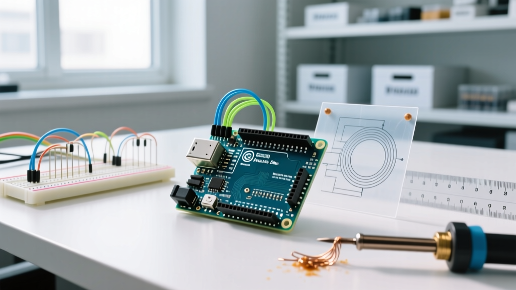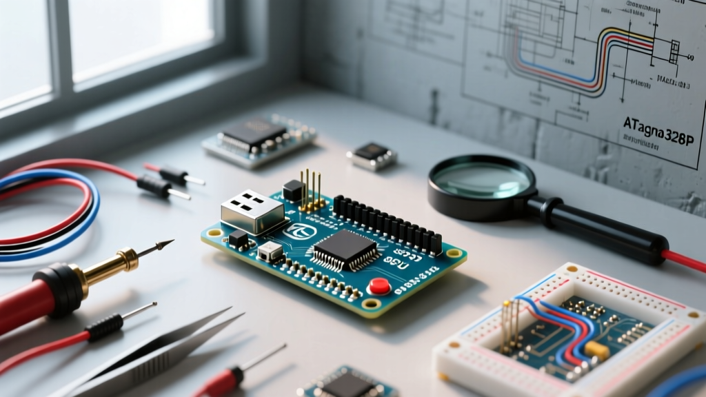

Why the Arduino Nano Development Board?
When transitioning from blink-and-buzz tutorials to building permanent, space-constrained projects, the Arduino Nano development board is the undisputed champion of the maker workbench. While the Arduino Uno is excellent for prototyping with jumper wires, its bulky DIP socket and large footprint make it impractical for embedding into enclosures or mounting on custom PCBs. The Nano solves this by packing the exact same ATmega328P microcontroller into a breadboard-friendly, 0.3-inch wide footprint.
In 2026, the Nano ecosystem has expanded, but the classic ATmega328P-based board remains the most documented and accessible entry point for beginners. This guide will walk you through the hardware anatomy, the critical differences between official and clone boards, and the exact troubleshooting steps needed to get your first sketch running without pulling your hair out.
Hardware Anatomy: What is Actually on the Board?
Before wiring up sensors, you need to understand the silicon limitations of the board. According to the official Arduino Nano Documentation, the classic board relies on the Microchip ATmega328P-AU (surface mount) microcontroller. Here are the hard specifications you must keep in mind when designing your circuits:
- Operating Voltage: 5V (Logic levels are 5V; connecting 3.3V I2C sensors directly will fry them).
- Input Voltage (Recommended): 7V to 12V via the VIN pin.
- Flash Memory: 32 KB (ATmega328P), of which 0.5 KB is used by the bootloader.
- SRAM: 2 KB (This is where your variables live; running out of SRAM causes silent reboots).
- EEPROM: 1 KB (Non-volatile storage for settings that survive power loss).
- Clock Speed: 16 MHz.
- Digital I/O Pins: 14 (of which 6 provide PWM output).
- Analog Input Pins: 8 (A0 through A7, a distinct advantage over the Uno, which only breaks out A0-A5).
Official vs. Clone: The USB-to-Serial Divide
If you purchase an official Arduino Nano, it utilizes the FTDI FT232RL chip for USB-to-serial conversion. However, the market is flooded with third-party clones (often priced between $3 and $5, compared to the official $24.50 price tag). These clones almost universally replace the expensive FTDI chip with the WCH CH340G or CH340C chip.
Beginner Warning: The CH340 chip is perfectly capable and reliable, but it requires a specific driver installation on Windows 11 and older macOS systems before the Arduino IDE will recognize the COM port. Always check your Device Manager if your board isn't showing up.
If you are using a CH340-based clone, refer to the SparkFun CH340 Driver Installation Guide to get your system configured correctly before opening the IDE.
Comparison Matrix: Choosing Your Nano Variant
Arduino has recently expanded the Nano family. If you are buying new in 2026, you might wonder if the classic is still the right choice. Here is how the classic Nano development board stacks up against its modern siblings:
| Feature | Classic Nano (ATmega328P) | Nano Every | Nano RP2040 Connect |
|---|---|---|---|
| Microcontroller | ATmega328P | ATmega4809 | Raspberry Pi RP2040 |
| Flash / RAM | 32KB / 2KB | 48KB / 6KB | 16MB / 264KB |
| Price (Approx) | $24.50 (Clone: ~$4) | $11.50 | $21.00 |
| Best For | Legacy code, 5V logic, vast tutorial availability | More memory, 5V logic, no bootloader issues | Wi-Fi/Bluetooth, MicroPython, high-speed I/O |
Verdict: For absolute beginners following standard online tutorials, the classic ATmega328P Nano remains the most frictionless choice due to the sheer volume of legacy code and 5V compatibility.
Breadboard Wiring Best Practices
The primary advantage of the Arduino Nano development board is its 0.3-inch width. When you plug it into a standard solderless breadboard, it straddles the center trench perfectly, leaving exactly one row of holes exposed on each side for your jumper wires.
Power Rail Management
Do not rely on the Nano's onboard 5V regulator to power high-current components like servo motors or long LED strips. The onboard AMS1117-5.0 linear regulator can only safely dissipate about 150mA to 200mA of current before overheating. Always use a dedicated external 5V buck converter for peripherals that draw more than 100mA, tying the grounds together at a single star point to prevent ground loops and analog sensor noise.
Step-by-Step: IDE 2.x Setup and Bootloader Selection
Getting code onto the Nano is where 90% of beginners hit their first roadblock. Follow the Arduino IDE v2 Installation Guide first, then follow these exact steps:
- Connect the Nano to your PC using a data-capable Micro-USB cable (many cheap cables are power-only and will cause detection failures).
- Open Arduino IDE 2.x and navigate to Tools > Board > Arduino AVR Boards and select Arduino Nano.
- Navigate to Tools > Port and select the COM port (Windows) or /dev/cu.usbserial (Mac) associated with your board.
- The Bootloader Trap: Navigate to Tools > Processor. By default, the IDE selects "ATmega328P". However, 80% of cheap clones ship with the older, larger bootloader to save manufacturing costs. If your upload fails, change this setting to ATmega328P (Old Bootloader).
- Click the Upload arrow. The TX/RX LEDs on the Nano should flicker rapidly, indicating serial data transfer.
Real-World Troubleshooting: Fixing Common Nano Failures
When things go wrong, the IDE output console is your best diagnostic tool. Here are the most common hardware and software failure modes specific to the Nano.
1. The Dreaded avrdude: stk500_getsync() attempt 10 of 10 Error
This error means the IDE cannot communicate with the bootloader. Before assuming the board is dead, check these three things:
- Cable Check: Swap the Micro-USB cable. Charge-only cables lack the D+ and D- data lines.
- Processor Mismatch: Toggle between "ATmega328P" and "ATmega328P (Old Bootloader)" as described above.
- Serial Port Collision: Ensure no other software (like Cura, PrusaSlicer, or a serial monitor) is hogging the COM port.
2. Instant Board Death: The 5V Pin Injection Mistake
The Nano has two ways to receive power: the USB port/VIN pin, and the 5V pin. The VIN pin routes through the onboard voltage regulator. The 5V pin bypasses the regulator entirely. If you are powering your project with a 9V battery and you accidentally wire it to the 5V pin instead of the VIN pin, you will instantly overvoltage the ATmega328P, permanently destroying the microcontroller. Always double-check your multimeter readings before connecting external battery packs to the 5V rail.
3. Analog Pin A6 and A7 Quirks
Unlike the Arduino Uno, the Nano breaks out pins A6 and A7. However, on the ATmega328P-AU surface-mount chip, A6 and A7 are strictly analog inputs. They do not have internal pull-up resistors, and they cannot be used as digital I/O pins (you cannot use digitalWrite(A6, HIGH)). If you need extra digital pins, you must use an I/O expander like the MCP23017 instead of trying to force A6 and A7 into digital mode.
Next Steps for Your Project
Once you have successfully uploaded the standard "Blink" sketch and verified your COM port communication, you are ready to integrate real-world sensors. Start with I2C devices like the BME280 environmental sensor or the SSD1306 OLED display. Remember to use 4.7kΩ pull-up resistors on the SDA (A4) and SCL (A5) lines if your sensor module doesn't have them built-in. The Arduino Nano development board is a powerhouse of prototyping; treat its power limits with respect, and it will serve as the reliable brain for hundreds of your future DIY electronics projects.