
Evaluating the Arduino Mega 2560 Pin Configuration for Complex Projects
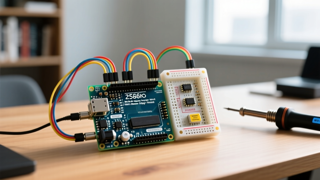
When prototyping complex electromechanical systems, the Arduino Mega 2560 remains a staple on engineering workbenches in 2026. While newer 32-bit microcontrollers boast higher clock speeds, the Mega 2560's sheer volume of accessible I/O pins keeps it highly relevant. However, simply having a high pin count does not guarantee suitability for every application. Understanding the nuanced Arduino Mega 2560 pin configuration—specifically its interrupt mapping, hardware serial routing, and power delivery limitations—is critical for avoiding catastrophic failure modes in advanced DIY builds, CNC routers, and 3D printers.
This project suitability analysis dissects the ATmega2560-16AU microcontroller's architecture to help you determine if this board aligns with your project's electrical and logical requirements, or if you should pivot to a modern alternative.
Anatomy of the ATmega2560 I/O Architecture
The Mega 2560 exposes 54 digital I/O pins and 16 analog inputs. However, treating all pins as functionally identical is a common engineering mistake. The underlying Microchip ATmega2560 datasheet reveals distinct hardware groupings that dictate how you should wire your peripherals.
Digital I/O, PWM, and Analog Mapping
Unlike the Uno, where PWM pins are scattered, the Mega 2560 groups its 15 Pulse Width Modulation (PWM) pins into two distinct banks: pins 2 through 13 and pins 44 through 46. If your project requires driving multiple DC motors or dimming high-power LED arrays, you must route these specific pins to your motor drivers (like the L298N or TB6612FNG).
Furthermore, the 16 analog pins (A0 through A15) can be repurposed as standard digital I/O pins (mapped to digital pins 54 through 69 in the Arduino IDE). This is highly useful for button matrices or limit switches when digital pins are exhausted, though they lack internal pull-up resistors on some older clone boards, requiring external 10kΩ resistors.
⚠️ The 5V Polyfuse and Regulator Trap:
A frequent failure mode in Mega 2560 projects is overloading the power rails. The onboard 5V linear regulator can safely dissipate heat up to roughly 800mA of total current draw before thermal shutdown. More critically, if powered via USB, a resettable polyfuse limits current to 500mA. Never wire high-torque servos (e.g., MG996R) or large LED strips directly to the Mega's 5V pin. Use a dedicated buck converter (like the LM2596) wired directly to the VIN or barrel jack circuit to bypass the onboard regulator.
Project Suitability Matrix
Not all projects benefit from the Mega's physical footprint. Below is a suitability analysis based on common complex project archetypes and how they leverage the specific Arduino Mega 2560 pin configuration.
| Project Archetype | Suitability | Pin Configuration Advantage | Primary Bottleneck / Edge Case |
|---|---|---|---|
| 3D Printers (Marlin) | Excellent | Maps perfectly to RAMPS 1.4/1.6 shields; utilizes multiple hardware serial ports for LCDs and Wi-Fi. | 8-bit 16MHz CPU struggles with complex Bezier curve calculations (Linear Advance) at high speeds. |
| CNC Routers (GRBL) | Moderate | Ample pins for dual-endstop limit switches, spindle relays, and probe inputs. | Standard GRBL is optimized for Uno (ATmega328P). Mega requires GRBL-Mega forks, complicating firmware updates. |
| Large LED Matrices | Poor | High pin count allows direct driving of shift registers (74HC595). | Lack of DMA (Direct Memory Access) and low SRAM (8KB) causes severe flickering on high-res matrices. |
| Automated Weather Stations | Good | Hardware I2C and SPI allow simultaneous connection of anemometers, rain gauges, and SD card loggers. | High power consumption (~50mA active) makes it unsuitable for long-term solar/battery deployments without sleep mods. |
Interrupt Mapping and Encoder Edge Cases
For projects involving rotary encoders, flow meters, or high-speed RPM tracking, hardware interrupts are mandatory to prevent missed steps. The Arduino Mega 2560 pin configuration supports six external hardware interrupts, mapped to specific pins:
- INT0: Pin 2
- INT1: Pin 3
- INT2: Pin 21
- INT3: Pin 20
- INT4: Pin 19
- INT5: Pin 18
Expert Insight: Notice that pins 20 and 21 double as the hardware I2C (SDA/SCL) lines. If your project requires both an I2C OLED display and high-speed rotary encoders, you will face a pin conflict. You must either move the I2C bus to a software-based Wire library (which is prone to timing jitter) or use Pin Change Interrupts (PCINT) on other pins. While the ATmega2560 supports PCINT on almost all ports, the Arduino IDE does not natively expose them via attachInterrupt(). You must integrate third-party libraries like PinChangeInterrupt to handle PCINT vectors efficiently without bloating the 256KB flash memory.
Communication Bus Overlaps and Pin Conflicts
The Mega 2560 excels in multi-device communication, featuring four hardware UARTs (Serial, Serial1, Serial2, Serial3). This makes it ideal for projects requiring simultaneous GPS parsing, DMX512 lighting control, and Nextion HMI display rendering. However, the SPI and I2C configurations harbor hidden traps for the uninitiated.
The SPI Pin 53 Master Mode Trap
Hardware SPI is routed to pins 50 (MISO), 51 (MOSI), 52 (SCK), and 53 (SS). A notorious edge case occurs when developers use pin 53 for a generic digital I/O purpose (like toggling a relay) while simultaneously communicating with an SPI device like an SD card module or RFID reader.
According to the Marlin firmware hardware documentation and Atmel's architecture guidelines, if pin 53 is configured as an INPUT, the SPI hardware interface automatically drops out of Master mode and into Slave mode if the pin is pulled LOW. This silently kills SPI communication, resulting in corrupted SD card writes or unresponsive TFT displays. Rule of thumb: Always explicitly define pin 53 as an OUTPUT in your setup() function, even if you are using a different pin for your actual SPI Chip Select (CS) line.
When to Reject the Mega 2560: Modern Alternatives
While official Arduino Mega 2560 Rev3 boards retail around $48 in 2026, and high-quality clones (like Elegoo or HiLetgo) cost between $14 and $18, the hardware is fundamentally an 8-bit architecture designed in the mid-2000s. You should abandon the Mega 2560 pin configuration in favor of modern alternatives if your project exhibits the following requirements:
- High-Speed Signal Processing: If you are building a digital oscilloscope or processing audio via FFT, the 16MHz AVR chip is insufficient. The Teensy 4.1 (600MHz ARM Cortex-M7) offers vastly superior DSP capabilities and a similar high-pin-count form factor.
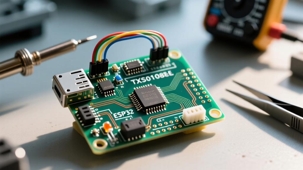
- Native 3.3V Logic and Wi-Fi: Interfacing the 5V Mega with modern 3.3V sensors (like the BME688 or modern LiDAR modules) requires cumbersome logic level shifters (e.g., TXS0108E), which introduce capacitance and ruin high-speed I2C/SPI edges. The ESP32-S3 provides native 3.3V logic, dual-core processing, and wireless connectivity, though it requires careful planning due to its lower total GPIO count and specific ADC pin limitations.
- True Analog Fidelity: The Mega's 10-bit ADC (yielding values 0-1023) is inadequate for precision load cells or medical-grade biometric sensors. Boards featuring 12-bit or 16-bit ADCs are mandatory for these use cases.
Final Verdict
The Arduino Mega 2560 pin configuration remains an unmatched workhorse for 5V-tolerant, I/O-heavy, low-frequency projects like 3D printer controllers, large-scale relay matrices, and educational robotics. By respecting its current limits, properly managing the SPI Pin 53 hardware quirk, and strategically mapping external interrupts, engineers can extract maximum reliability from this legacy platform. However, for high-speed, 3.3V, or wireless-native architectures, migrating to ARM-based alternatives is the only logical path forward.