
Why the Arduino Mega 2560 Still Dominates I/O-Heavy Projects
While modern 32-bit boards like the ESP32 and Raspberry Pi Pico have captured the wireless and edge-computing markets, the Arduino Mega 2560 remains the undisputed heavyweight for robotics, CNC controllers, and multi-sensor arrays. With 54 digital I/O pins (15 of which can be used as PWM outputs), 16 analog inputs, and a massive 256 KB of flash memory, it eliminates the need for complex I/O multiplexers in large-scale DIY builds.
In this comprehensive setup and first-project tutorial, we will walk through the exact steps to configure your IDE, avoid common hardware traps, and build a robust multi-sensor environmental monitoring node.
Hardware Prerequisites & Authenticity Check
Before plugging anything in, you need to identify which version of the board you have. The market is flooded with variants, and your setup process will differ slightly depending on the USB-to-Serial chip used.
- Official Arduino Mega 2560 Rev3: Priced around $42 to $46. It uses the ATmega16U2 chip for USB communication. No external drivers are required on modern Windows/macOS systems.
- Third-Party Clones (Elegoo, HiLetgo, etc.): Priced between $14 and $18. These typically substitute the 16U2 with a CH340G USB-to-Serial chip to cut costs. You will need to install the CH340 driver manually.
- Sensors for this project: BME280 Environmental Sensor (I2C, ~$10) and a waterproof DS18B20 Temperature Probe (OneWire, ~$6).
- Cable: USB Type-A to Type-B (the standard "printer cable"). Do not use a micro-USB or USB-C cable; the Mega has not been updated to modern USB connectors.
Step 1: IDE Configuration and Driver Setup
Download the latest Arduino IDE 2.x from the official website. If you are using a clone board with a CH340 chip, download and install the CH340 driver from the manufacturer's repository before launching the IDE.
- Connect the Mega to your PC via the USB-B cable.
- Open the IDE and navigate to Tools > Board > Arduino AVR Boards and select Arduino Mega or Mega 2560.
- Under Tools > Processor, ensure ATmega2560 (Mega 2560) is selected. (Avoid the ATmega1280 option unless you are using a very rare, discontinued legacy board).
- Select the correct COM port under Tools > Port.
- Upload the default
Blinkexample to verify the toolchain is functioning.
Architecture Showdown: Mega 2560 vs. Uno R4 Minima
Why choose the aging 8-bit Mega over the modern 32-bit Uno R4? The answer lies in raw pin count and legacy shield compatibility. Below is a technical comparison to help you finalize your platform choice.
| Feature | Arduino Mega 2560 | Arduino Uno R4 Minima |
|---|---|---|
| Microcontroller | ATmega2560 (8-bit AVR) | RA4M1 (32-bit ARM Cortex-M4) |
| Operating Voltage | 5V | 5V |
| Flash Memory | 256 KB | 256 KB |
| SRAM | 8 KB | 32 KB |
| Digital I/O Pins | 54 | 14 |
| Analog Input Pins | 16 (10-bit ADC) | 6 (14-bit ADC) |
| Hardware Serial Ports | 4 (UARTs) | 1 (plus software USB) |
Step 2: Wiring the Multi-Sensor Environmental Node
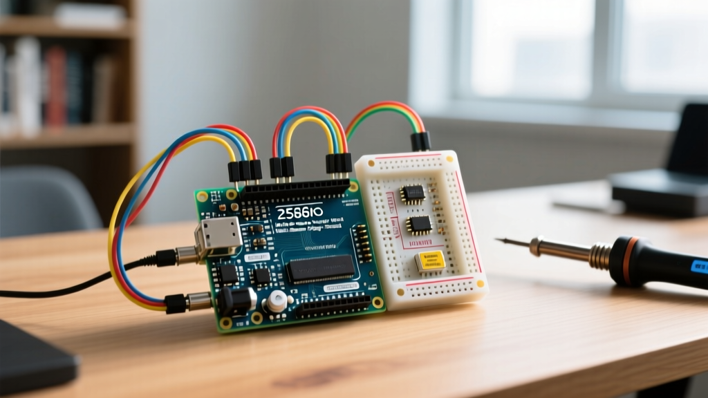
Our first project will read temperature, humidity, and barometric pressure from the BME280, alongside a secondary waterproof temperature reading from the DS18B20.
The I2C Pin Trap (Crucial Edge Case)
The most common mistake beginners make when migrating from the Uno to the Mega is I2C wiring. On the Uno, SDA is A4 and SCL is A5. On the Arduino Mega, SDA is Pin 20 and SCL is Pin 21. While the R3 revision duplicated these on the A4/A5 headers for specific shield compatibility, relying on pins 20 and 21 guarantees stable, direct routing to the TWI (Two-Wire Interface) hardware.
Wiring Matrix
- BME280 VCC to Mega 3.3V (Do not use 5V; the BME280 is strictly a 3.3V logic device, and 5V will degrade the sensor over time).
- BME280 GND to Mega GND.
- BME280 SDA to Mega Pin 20.
- BME280 SCL to Mega Pin 21.
- DS18B20 VCC (Red) to Mega 5V.
- DS18B20 GND (Black) to Mega GND.
- DS18B20 Data (Yellow/White) to Mega Pin 22.
- Pull-up Resistor: Place a 4.7kΩ resistor between the DS18B20 Data line and the 5V line. Without this, the OneWire bus will float and return -127°C errors.
Step 3: The Data Logging Sketch
Install the Adafruit BME280 Library and the DallasTemperature (plus OneWire) libraries via the Library Manager. Upload the following optimized sketch:
#include <Wire.h>
#include <Adafruit_BME280.h>
#include <OneWire.h>
#include <DallasTemperature.h>

Adafruit_BME280 bme;
OneWire oneWire(22);
DallasTemperature sensors(&oneWire);

void setup() {
  Serial.begin(115200);
  while(!Serial); // Wait for serial monitor

  if (!bme.begin(0x76)) { // Default I2C address is usually 0x76 or 0x77
    Serial.println("BME280 initialization failed. Check wiring!");
    while (1);
  }
  sensors.begin();
}

void loop() {
  sensors.requestTemperatures();
  float probeTempC = sensors.getTempCByIndex(0);

  Serial.print("Ambient Temp: "); Serial.print(bme.readTemperature()); Serial.println(" C");
  Serial.print("Humidity: "); Serial.print(bme.readHumidity()); Serial.println(" %");
  Serial.print("Pressure: "); Serial.print(bme.readPressure() / 100.0F); Serial.println(" hPa");
  Serial.print("Probe Temp: "); Serial.print(probeTempC); Serial.println(" C");
  Serial.println("------------------------");

  delay(2000);
}
Power Architecture Edge Cases & Thermal Limits
Expert Warning: The onboard NCP1117 5V linear regulator on the Mega 2560 is limited by thermal dissipation. If you power the board via the barrel jack at 12V, the voltage drop across the regulator is 7V. At this differential, you can safely draw a maximum of ~125mA from the 5V pin before the regulator overheats and triggers thermal shutdown. For servo-heavy or LED-heavy projects, bypass the onboard regulator and inject a regulated 5V source directly into the 5V pin.
For deeper hardware specifications, always refer to the official Microchip ATmega2560 datasheet to understand register-level configurations and absolute maximum ratings.
Troubleshooting the Dreaded 'stk500v2' Timeout
If you encounter the avrdude: stk500v2_ReceiveMessage(): timeout error during upload, your board's auto-reset circuit is failing to trigger the bootloader. This is incredibly common on third-party clones due to missing or mismatched capacitors on the DTR line.
The 10µF Capacitor Fix:
- Locate the
RESETpin and the5Vpin on the digital header. - Insert a 10µF electrolytic capacitor between them (Positive leg to RESET, Negative leg to 5V).
- This disables the auto-reset feature. You must now manually press the physical RESET button on the board exactly when the IDE console says "Uploading..." to catch the bootloader window.
Alternatively, if the board fails to enumerate on USB entirely, check the USB-B connector's shield pins. Clone manufacturers frequently suffer from cold solder joints on the heavy USB connector, leading to intermittent power and data failures. A quick reflow with a flux-cored 60/40 solder wire usually resolves physical connection drops.
Next Steps and Expansion
With your Arduino Mega successfully configured and reading multi-bus sensor data, you are ready to scale. The 4 hardware UARTs (Serial, Serial1, Serial2, Serial3) allow you to connect GPS modules, cellular modems, and Nextion HMI displays simultaneously without relying on fragile SoftwareSerial libraries. For complete pin mapping and advanced interrupt configurations, consult the Arduino Mega 2560 Official Documentation.