
Why Your HC-SR04 is Failing: Beyond Basic Code
When an ultrasonic distance sensor starts throwing erratic values, returning constant zeros, or freezing your microcontroller, the immediate instinct is to blame the code. However, 90% of HC-SR04 integration failures stem from ignoring the physical and electrical boundaries defined in the hc sr04 sensor datasheet. While hobbyist tutorials often gloss over the raw timing diagrams and logic-level thresholds, professional embedded engineers rely on these exact specifications to design robust, noise-resistant systems.
This troubleshooting guide bypasses generic advice and dives deep into the silicon and acoustic realities of the HC-SR04. By aligning your hardware design and firmware logic with the manufacturer's datasheet, you can eliminate timeout errors, protect 3.3V microcontrollers, and achieve millimeter-level reliability.
Decoding the Measurement Cycle: Critical Timings
The HC-SR04 does not output a continuous stream of data. It operates on a strict, request-response protocol governed by microsecond-level timing. Understanding this sequence is the first step in debugging a frozen or unresponsive sensor.
The 10µs Trigger Pulse Requirement
According to the datasheet, the module requires a TTL pulse of at least 10 microseconds (µs) on the Trigger pin to initiate a measurement cycle. If your microcontroller is handling heavy interrupt loads (such as PWM motor control or Wi-Fi stack management on an ESP32), a standard digitalWrite() sequence might be interrupted, resulting in a malformed 4µs or 6µs pulse. The sensor's internal controller will simply ignore this invalid trigger.
Expert Firmware Fix: Wrap your trigger pulse in a
noInterrupts()andinterrupts()block to guarantee a clean, uninterrupted 10µs HIGH state. Always pull the trigger LOW for at least 2µs beforehand to ensure a clean rising edge.
The 40kHz Burst and Echo High-Time
Once triggered, the module emits an eight-cycle burst of ultrasound at 40kHz. The Echo pin immediately goes HIGH. The duration of this HIGH state is directly proportional to the time it takes for the acoustic wave to travel to the target and back. The datasheet defines the conversion factor as 58µs per centimeter (or 147µs per inch). If your target is 100cm away, the Echo pin will remain HIGH for exactly 5,800µs (5.8ms).
If you are using the Arduino pulseIn() function, failing to set an appropriate timeout parameter will cause your microcontroller to halt execution for up to 1 second if the acoustic wave never returns (e.g., absorbed by soft foam). Always set your timeout to 25000 (25ms), which corresponds to the sensor's maximum theoretical range of ~400cm.
Voltage Logic Mismatches: The 3.3V vs 5V Trap
The most catastrophic mistake documented in field failures involves power and logic levels. The HC-SR04 is a 5V device. Its Echo pin outputs a 5V TTL signal when HIGH. If you connect this directly to a 3.3V microcontroller (like the ESP32, STM32, or Raspberry Pi Pico), you risk permanently damaging the GPIO pin due to overvoltage, or you will experience severe phantom readings caused by floating logic thresholds.
While the Trigger pin is an input and will usually recognize a 3.3V signal as HIGH (since the HC-SR04's TTL threshold is typically around 2.0V), the Echo pin requires a logic level shifter or a simple voltage divider.
| Resistor R1 (Series) | Resistor R2 (Ground) | Output Voltage (from 5V Echo) | Use Case |
|---|---|---|---|
| 1.0 kΩ | 2.0 kΩ | ~3.33V | ESP32 / ESP8266 |
| 1.5 kΩ | 2.2 kΩ | ~3.08V | STM32 / Raspberry Pi Pico |
| 3.3 kΩ | 5.1 kΩ | ~3.12V | Low-Power Battery Nodes |
Note: Keep resistor values relatively low (under 10kΩ total) to ensure the RC time constant doesn't round off the sharp edges of the Echo pulse, which can introduce microsecond-level measurement errors.
Physical Limitations Dictated by the Datasheet
No amount of code optimization can overcome the laws of acoustics. The HC SR04 sensor datasheet outlines strict physical boundaries that dictate where and how the sensor can be mounted.
The 2cm Blind Zone
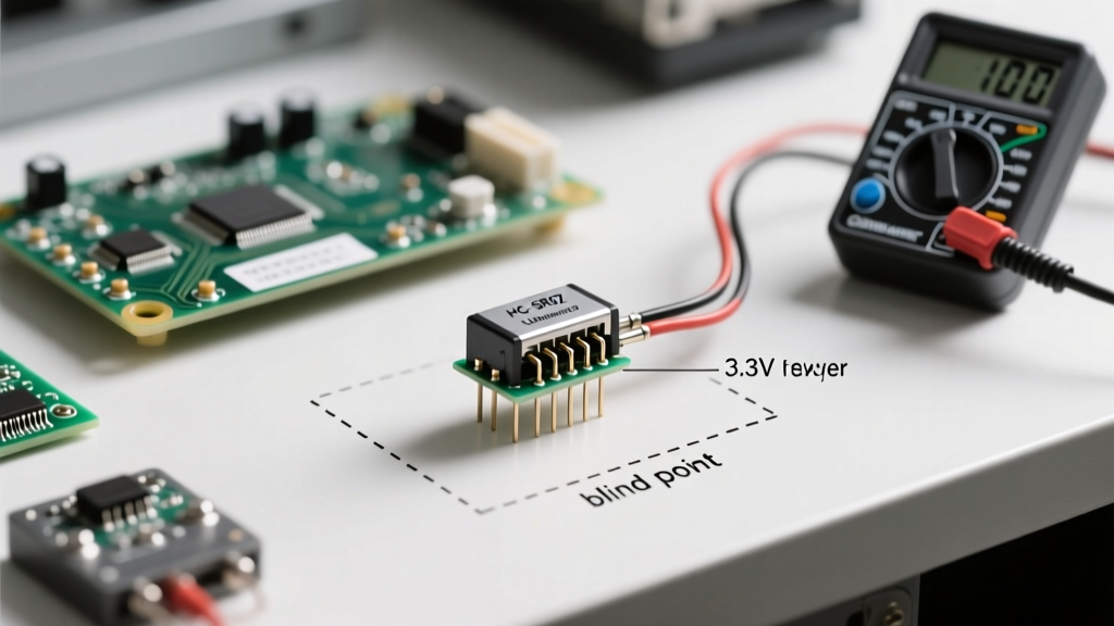
The sensor has a minimum effective range of 2cm. If an object is placed closer than this, the returning echo overlaps with the initial 40kHz transmit burst. The internal comparator cannot distinguish between the outgoing ring and the incoming reflection, resulting in a default output of 0cm or a locked HIGH state. If your application requires sub-2cm detection, you must switch to an infrared Time-of-Flight (ToF) sensor like the VL53L0X.
Beam Angle and Acoustic Shadows
The datasheet specifies a cone angle of roughly 15 degrees to either side of the central axis (30 degrees total). However, this is measured at the -6dB drop-off point. In reality, the sensor will pick up specular reflections from objects outside this cone if they are highly reflective (like flat glass or polished metal). To prevent "ghost readings" from nearby walls, mount the sensor in a neoprene or foam shroud to dampen side-lobe acoustic leakage.
Troubleshooting Matrix: Symptoms vs. Datasheet Specs
Use this diagnostic matrix to map your specific failure mode to a datasheet violation.
| Symptom | Datasheet Violation / Root Cause | Hardware / Firmware Solution |
|---|---|---|
| Constant 0cm Readings | Object inside 2cm blind zone OR Echo pin shorted/fried by 5V logic. | Verify physical clearance; check voltage divider with a multimeter. |
| Random Massive Spikes (e.g., 3000cm) | Acoustic interference from another 40kHz source or crosstalk between multiple sensors. | Stagger sensor triggers by 50ms; implement a software median filter. |
| Sensor Freezes / Echo stays HIGH | Acoustic wave absorbed by soft material; no echo returned to reset the flip-flop. | Enforce a hard timeout in pulseIn(); power cycle the sensor via a MOSFET if locked. |
| Readings Drift with Temperature | Speed of sound changes with temperature (datasheet assumes 20°C / 343 m/s). | Add a DS18B20 temp sensor and dynamically adjust the 58µs/cm multiplier in code. |
Power Delivery and Decoupling Capacitors
A frequently overlooked section of the hc sr04 sensor datasheet is the power consumption profile. The module draws roughly 2mA in standby, but during the 40kHz transmit burst, current draw spikes to 15mA to 20mA. If you are powering the sensor directly from a microcontroller's onboard 5V linear regulator (which may already be struggling to power Wi-Fi radios or LEDs), this sudden 15mA spike causes a momentary voltage sag (brownout).
This sag can reset the sensor's internal logic right in the middle of a measurement cycle, leading to corrupted Echo pulses. Furthermore, if the 5V rail drops below 4.5V during the burst, the acoustic output power drops, shrinking your maximum reliable range.
Pro-Tip for PCB Design: Always place a 100µF electrolytic capacitor and a 0.1µF ceramic decoupling capacitor as close to the HC-SR04 VCC and GND pins as physically possible. This local energy reservoir handles the transient 15mA spike without pulling down the main system voltage rail.
Advanced Filtering for Noisy Environments
Even with perfect hardware, industrial environments introduce acoustic noise. The HC-SR04 module lacks onboard digital signal processing (DSP). It relies on a simple analog comparator to detect when the returning 40kHz wave crosses a voltage threshold. High-frequency vibrations from motors or pneumatic valves can trigger this comparator prematurely.
To combat this, abandon simple averaging algorithms. A single anomalous reading will skew a standard mean average. Instead, implement a Rolling Median Filter in your firmware. By storing the last 5 to 7 readings in an array, sorting them, and selecting the middle value, you mathematically eliminate the outliers caused by acoustic noise without introducing the phase lag associated with heavy low-pass filtering.
Conclusion
Troubleshooting the HC-SR04 is rarely about rewriting your distance calculation math; it is about respecting the physical and electrical constraints outlined in the hc sr04 sensor datasheet. By guaranteeing clean 10µs trigger pulses, properly translating 5V logic down to 3.3V, respecting the 2cm blind zone, and stabilizing the power rail with decoupling capacitors, you transform a frustrating hobbyist component into a highly reliable industrial ranging tool.