
The Anatomy of a Digital Multimeter (DMM)
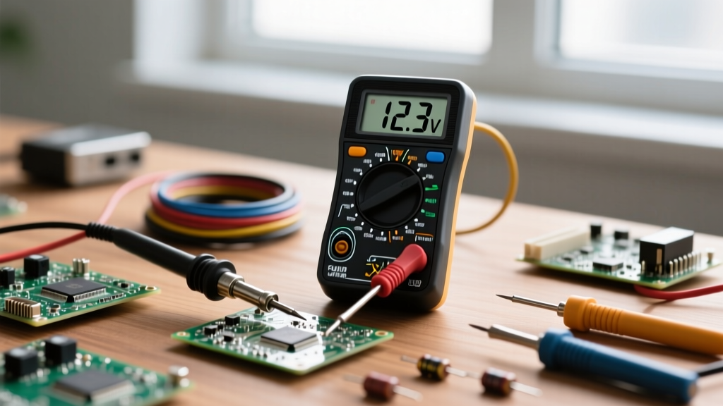
Before you can safely measure a circuit, you need to understand the tool in your hand. A digital multimeter (DMM) is the most fundamental piece of test equipment for any electrician, electronics hobbyist, or DIYer. According to SparkFun's comprehensive electronics tutorials, mastering the DMM is the first step toward debugging and building reliable circuits.
The Three Critical Ports
Look at the bottom of your multimeter. You will typically see three or four input jacks. Plugging your test leads into the wrong jacks is the most common way beginners destroy their equipment.
- COM (Common): This is your ground or reference point. The black probe always stays here, regardless of what you are measuring.
- V/Ω/mA (Voltage, Resistance, Milliamps): The red probe goes here for measuring voltage, resistance, continuity, and small currents (usually under 200mA to 400mA). This port is protected by an internal fuse.
- 10A (High Current): The red probe moves here only when measuring large currents (above 400mA, up to 10 Amps). Warning: This port is often unfused on budget multimeters. Connecting it across a voltage source will cause a dead short, potentially melting your probes or causing an arc flash.
Safety First: Understanding CAT Ratings
Not all multimeters are created equal. If you are working on household wiring or automotive systems, you must understand Measurement Categories (CAT ratings). As detailed in Fluke's official safety guidelines, CAT ratings define the tool's ability to withstand transient voltage spikes (surges) without exploding.
- CAT II: Safe for single-phase receptacle connected loads (e.g., testing a toaster, TV, or power drill).
- CAT III: Safe for three-phase distribution, including single-phase commercial lighting and fixed motor loads. Required for testing household breaker panels and hardwired appliances.
- CAT IV: Safe for three-phase utility connections and outdoor service entrances.
Pro Tip: Always inspect your test probes before use. If the silicone insulation is cracked or the metal tips are exposed beyond the finger guards, discard them immediately. A compromised probe can lead to severe electrical shock when working on mains voltage.
Step 1: Measuring DC Voltage (The Battery Test)
Direct Current (DC) voltage flows in one direction, typical of batteries and solar panels. This is the safest and easiest measurement for beginners.
- Insert the black probe into the COM port and the red probe into the V/Ω port.
- Turn the dial to the DC Voltage setting. This is denoted by a V with a solid line and three dashed lines beneath it (⎓). If your DMM is manual-ranging, select a range higher than your expected voltage (e.g., select 20V to test a 12V car battery).
- Touch the red probe to the positive (+) terminal and the black probe to the negative (-) terminal.
Reading the Display: A fresh alkaline AA battery will read approximately 1.58V. A fully charged 12V automotive battery should read between 12.4V and 12.7V at rest. If you see a negative sign (e.g., -12.6V), don't panic; it simply means your probes are reversed. Swap them to get a positive reading.
Step 2: Testing Continuity (The Beep Test)
Continuity testing checks if a complete electrical path exists between two points. It is invaluable for finding broken wires, blown fuses, or verifying solder joints.
- Turn the dial to the continuity symbol, which looks like a series of sound waves or a diode symbol with sound waves.)
- Touch the two metal probe tips together. You should hear a distinct beep, and the display should read close to 0.00Ω.
- Place the probes on either end of a fuse or a switch. If it beeps, the circuit is closed (good). If it remains silent and displays 'OL', the circuit is broken (bad).
Crucial Rule: Never test continuity on a live circuit. The presence of voltage can blow the internal fuse of your multimeter or damage the continuity testing circuitry. Always disconnect power before testing.
Step 3: Measuring Resistance (Ohms)
Resistance measures how much a component opposes the flow of current, measured in Ohms (Ω). This is used to verify the value of resistors or check the health of heating elements.
- Ensure the component is completely removed from the circuit, or at least that power is OFF and capacitors are discharged.
- Set the dial to the Omega (Ω) symbol.
- Touch the probes to the two legs of the resistor. The reading will stabilize after a second.
If the screen displays OL (Over Limit), it means the resistance is higher than the selected range. Switch to a higher range (e.g., from 2kΩ to 20kΩ or 2MΩ) until a numerical value appears.
Step 4: Measuring Current (The Danger Zone)
Measuring current (Amps) is fundamentally different from measuring voltage. While voltage is measured in parallel (across a component), current must be measured in series (the current must flow through the multimeter).
Why Blowing the Internal Fuse Happens
The most common way beginners destroy a multimeter is by leaving the red probe in the 'A' (Amps) port and then touching the probes across a voltage source (like a wall outlet or battery). Because the current port has near-zero resistance, this creates a dead short circuit. The multimeter will attempt to draw maximum current, instantly blowing its internal High Rupturing Capacity (HRC) fuse—or worse, causing a fire if the meter lacks proper protection.
- Determine if your current will be high (above 400mA) or low. Move the red probe to the appropriate A or mA port.
- Set the dial to Amps (A⎓ for DC, A~ for AC).
- Break the circuit. You must disconnect a wire in your circuit and use the multimeter probes to bridge the gap, forcing the electricity to flow through the meter to reach the load.
Auto-Ranging vs. Manual-Ranging: Which Should You Buy?
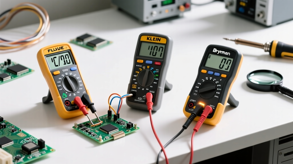
When shopping for your first DMM, you will encounter two main architectures. Here is a comparison to help you decide.
| Feature | Manual-Ranging DMM (e.g., AstroAI DM6000AR) | Auto-Ranging DMM (e.g., Fluke 115 / Klein MM400) |
|---|---|---|
| Operation | User must select the specific scale (e.g., 2V, 20V, 200V). | Meter automatically detects and selects the correct scale. |
| Speed | Instant reading once the correct range is selected. | Takes 1-3 seconds to 'lock onto' the correct range. |
| Learning Curve | Higher. Teaches you the order of magnitude of circuits. | Lower. Much easier for beginners to just 'plug and play'. |
| Price | Budget-friendly ($15 - $40). | Mid to High ($40 - $200+). |
| Best For | Students, hobbyists on a strict budget. | Professionals, DIYers who value convenience and safety. |
Common Beginner Mistakes and Troubleshooting
Even with a solid understanding of the basics, beginners frequently run into frustrating issues. Here is how to troubleshoot the most common DMM errors:
- The Display Reads '1' or 'OL' Immediately: This means 'Overload' or 'Out of Limits'. You are either trying to measure a voltage higher than your current range setting, or you are testing an open circuit in resistance/continuity mode. Increase your range or check your connections.
- Fluctuating or 'Ghost' Voltage Readings: If you are measuring a disconnected wire and see a small, wandering AC voltage (e.g., 10V to 40V), you are likely experiencing capacitive coupling from adjacent live wires in the same wall cavity. High-impedance DMMs will pick up this 'ghost voltage'. Professional meters like the Fluke 117 feature a 'LoZ' (Low Impedance) mode specifically designed to bleed off this ghost voltage and show a true zero.
- Sluggish Response Times: If your meter takes several seconds to update, the internal 9V battery is likely dying. A low battery can also cause wildly inaccurate readings. Always replace the battery when the low-battery icon appears on the LCD.
Mastering how to use a digital multimeter is a rite of passage for anyone working with electronics or electrical systems. By respecting the CAT safety ratings, understanding the physical ports, and methodically breaking circuits for current measurements, you will ensure both your safety and the longevity of your diagnostic tools.