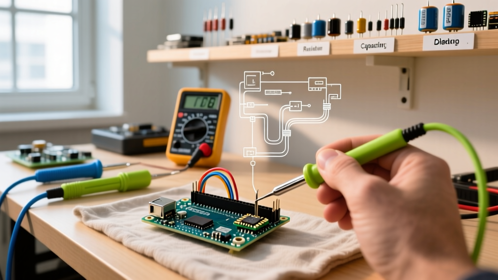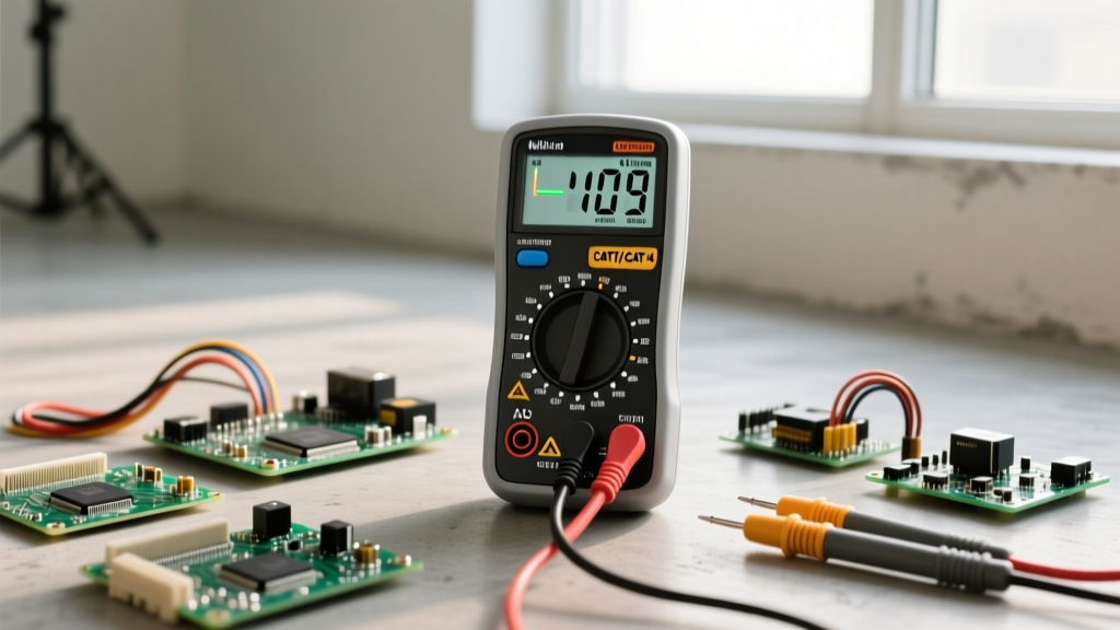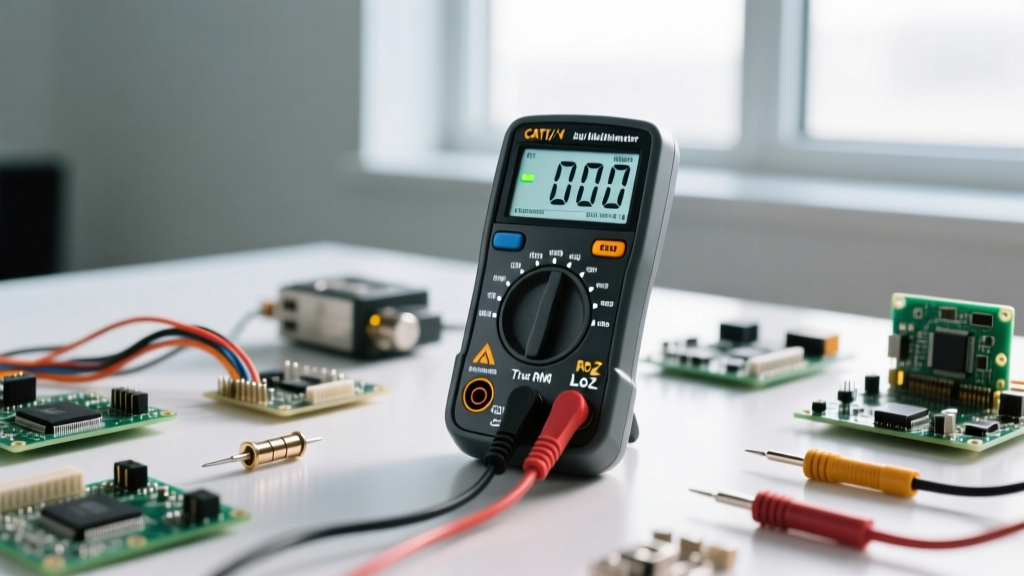

The Anatomy of a Modern Digital Multimeter (DMM)
Proper multimeter use is the dividing line between a frustrated hobbyist and a confident DIY electronics engineer. Whether you are debugging a custom PCB, wiring a smart home relay, or simply checking if a 9V battery is dead, your digital multimeter (DMM) is your primary window into the invisible world of electricity. But a DMM is not just a simple measuring stick; it is a complex piece of diagnostic equipment with specific internal architectures that dictate how it interacts with your circuits.
At its core, a modern DMM relies on an Analog-to-Digital Converter (ADC) to translate continuous electrical signals into discrete numerical values on the LCD screen. When you set the dial to measure voltage, you are routing the signal through a high-impedance voltage divider network. Most standard multimeters feature an input impedance of 10 MΩ (megohms) on their voltage ranges. This high impedance ensures that the meter draws virtually zero current from the circuit under test, preventing the meter itself from altering the behavior of high-impedance sensor circuits or voltage dividers.
Essential Multimeter Use Cases for DIY Projects
To master multimeter use, you must understand the three fundamental measurements: potential difference (voltage), electron flow (current), and path integrity (continuity). Let us break down the practical application of each in a real-world maker environment.
1. Measuring DC Voltage: The Logic Level Check
Voltage is the electrical pressure pushing electrons through a conductor. In DIY microcontroller projects, verifying DC voltage is the first step in power rail troubleshooting. If your Arduino Nano or ESP32 is randomly resetting, your first move should be probing the 5V or 3.3V pins.
- Black Probe: Always connects to the COM (Common) port and the circuit's ground (GND).
- Red Probe: Connects to the VΩmA port and the test point.
- Expected Readings: A healthy USB-powered 5V rail should read between 4.8V and 5.2V. If you read 4.2V, you are likely experiencing excessive voltage drop across a thin USB cable or an overloaded linear regulator.
Pro Tip: If you are measuring AC mains voltage (like a 120V wall outlet or a 24VAC HVAC transformer), ensure your meter is set to AC Voltage (V~) and that you are using a meter with the appropriate CAT safety rating, which we will cover later.
2. Testing Continuity: Hunting Down Broken Traces
Continuity testing is arguably the most frequently used function in DIY electronics. It answers a simple binary question: Is there a complete electrical path between point A and point B?
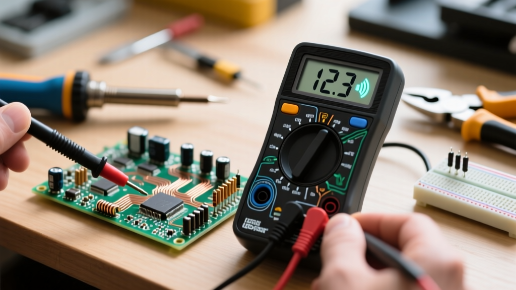
When you switch to continuity mode (usually denoted by a soundwave symbol), the meter sends a tiny, safe current through the probes. If the resistance between the probes is below a specific threshold (typically 30 to 50 ohms), the internal piezo buzzer sounds. This is invaluable for:
- Verifying solder joints on DIY perfboards.
- Checking if a fuse is blown without removing it from the holder.
- Mapping out unknown pinouts on ribbon cables or salvaged connectors.
Critical Warning: Never test continuity on a live, powered circuit. The external voltage will confuse the meter's internal logic, potentially blowing the internal fuse or damaging the ADC. Always discharge capacitors and remove power before testing continuity.
3. Measuring Current: The Serial Break Method
Current measurement (Amps) is where most beginners make catastrophic mistakes. Unlike voltage, which is measured in parallel, current must be measured in series. You must physically break the circuit and force the electrons to flow through the multimeter.
Inside the meter's 10A port, there is a shunt resistor—typically a thick piece of manganin or nichrome wire with a very low resistance (e.g., 0.01 Ω). The meter measures the voltage drop across this shunt and uses Ohm's Law (I = V/R) to calculate the current. Because this shunt generates heat, budget multimeters often limit 10A measurements to 30 seconds to prevent the internal traces from melting.
Understanding Burden Voltage and Measurement Errors
When measuring current on the mA or µA ranges, the multimeter uses a much higher value shunt resistor to generate a measurable voltage drop. This introduces a phenomenon known as burden voltage.
For example, if your meter has a burden voltage of 1mV per µA, and you are measuring a 20mA circuit, the meter will drop 20mV. If your circuit is a low-voltage, low-power sensor running on a 1.8V coin cell, that 20mV drop might be enough to push the microcontroller into a brownout reset. In these ultra-low-power DIY scenarios, consider using a specialized current shunt and an oscilloscope, or a dedicated current monitor IC like the INA219, rather than relying on standard multimeter use for current tracking.
Common Beginner Mistakes and How to Avoid Blowing Your Fuse
The most common way to destroy a multimeter is by attempting to measure voltage while the red probe is plugged into the current (A or mA) port. Because the current port contains a near-zero resistance shunt, placing it across a voltage source creates a dead short.
If you do this across a 12V battery, you will instantly blow the internal glass fuse. If you do this across a 120V AC mains outlet, the resulting arc flash can vaporize the thin glass fuse, ionize the air inside the meter, and cause the plastic housing to explode in your hands. This is why professional meters use HRC (High Rupturing Capacity) ceramic fuses filled with sand to quench the arc safely.
Tool Comparison: Budget vs. Professional DMMs for Makers
Not all multimeters are created equal. The table below compares three popular tiers of multimeters for DIYers, highlighting the differences in safety, resolution, and advanced features.
| Feature | AstroAI AM33D (Budget) | Uni-Trend UT61E+ (Prosumer) | Fluke 115 (Professional) |
|---|---|---|---|
| Approx. Price | $15 | $65 | $210 |
| Display Counts | 2,000 | 22,000 | 6,000 |
| True RMS | No (Average Responding) | Yes (AC+DC) | Yes (AC) |
| Safety Rating | CAT III 600V (Unverified) | CAT III 600V / CAT II 1000V | CAT III 600V (Independent Lab Verified) |
| Internal Protection | Glass fuses, basic PTC | HRC Fuses, MOV protection | HRC Fuses, 10kA fault protection |
| Best For | Low-voltage Arduino/battery projects | Advanced PCB debugging, audio DIY | Mains wiring, automotive, field repair |
For pure 5V microcontroller work, the AstroAI is sufficient. However, if your DIY projects involve soldering AC-to-DC switching power supplies or working with 120V/240V smart home relays, investing in a verified CAT III meter like the Fluke 115 or a highly-rated Uni-Trend is a non-negotiable safety requirement.
Advanced Troubleshooting: Using the Diode Test Mode
Beyond basic continuity, the diode test mode is a secret weapon for component-level troubleshooting. In this mode, the meter outputs a constant current (usually 1mA to 2mA) and measures the forward voltage drop across the component.
- Silicon Diodes (e.g., 1N4007): Expect a reading of 0.5V to 0.7V.
- Schottky Diodes (e.g., 1N5819): Expect a lower drop, typically 0.2V to 0.3V.
- LEDs: A red LED will show ~1.8V, while a blue or white LED will show ~2.8V to 3.2V. (Note: Some meters do not output enough open-circuit voltage to fully illuminate blue/white LEDs, but the reading will still be accurate).
- Transistors (BJT): You can use diode mode to identify the Base, Collector, and Emitter pins of an unknown bipolar junction transistor by mapping the internal PN junctions.
Further Reading and Authoritative Resources
To deepen your understanding of diagnostic tools and safety standards, we recommend reviewing the official documentation from leading test equipment manufacturers. The SparkFun Multimeter Tutorial provides an excellent visual breakdown of probe placement and basic circuit theory. Additionally, for those working on higher-voltage DIY projects, the Fluke Guide to Multimeter Safety and Usage offers critical insights into CAT ratings, energy transients, and proper PPE (Personal Protective Equipment) when probing live mains circuits.
Mastering multimeter use is not just about reading numbers on a screen; it is about understanding the interaction between your test equipment and the circuit. By respecting the internal limitations of your DMM, utilizing the correct ports, and applying advanced modes like diode testing, you will drastically reduce your debugging time and elevate the quality of your DIY electronics projects.