
The Anatomy of a Voltage Reading: AC vs. DC
Voltage is the electrical potential difference between two points—essentially the "pressure" pushing electrons through a circuit. When troubleshooting a dead appliance, a flickering LED strip, or a faulty wall outlet, measuring this pressure is your first diagnostic step. However, before touching any probes to a circuit, you must understand the fundamental difference between the two types of voltage you will encounter.
Direct Current (DC) flows in a single, constant direction. You will find DC voltage in batteries, solar panels, automotive systems, and the low-voltage outputs of power adapters (like your laptop charger). On your multimeter dial, DC voltage is denoted by a V with a solid line and a dashed line beneath it (V⎓), or simply DCV.
Alternating Current (AC) periodically reverses direction. This is the power delivered by the grid to your home's wall outlets and heavy appliances. On your multimeter, AC voltage is denoted by a V with a wavy line (V~), or ACV. Mixing these settings up won't necessarily destroy a modern, auto-ranging digital multimeter (DMM), but it will result in a reading of zero or erratic numbers, leading to false troubleshooting conclusions.
Step-by-Step: How Do I Use a Multimeter to Check Voltage in DC Circuits?
When beginners ask, how do i use a multimeter to check voltage in a DIY electronics project or a car battery, they are usually dealing with DC. Here is the precise sequence for an accurate reading.
1. Probe Placement and Dial Selection
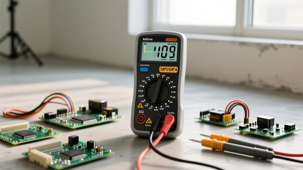
Insert the black probe into the COM (Common) port. Insert the red probe into the port labeled VΩmA (or simply V). Never leave the red probe in the high-current (10A) port when measuring voltage; doing so creates a dead short and will blow the multimeter's internal fuse or cause an arc flash.
Turn the dial to the DC Voltage setting (V⎓). If your multimeter is manual-ranging, select a range higher than the expected voltage. For example, if testing a 12V car battery, set the dial to 20V. If testing a 3.3V microcontroller pin, set it to 20V or 2V depending on your meter's increments.
2. Making the Connection
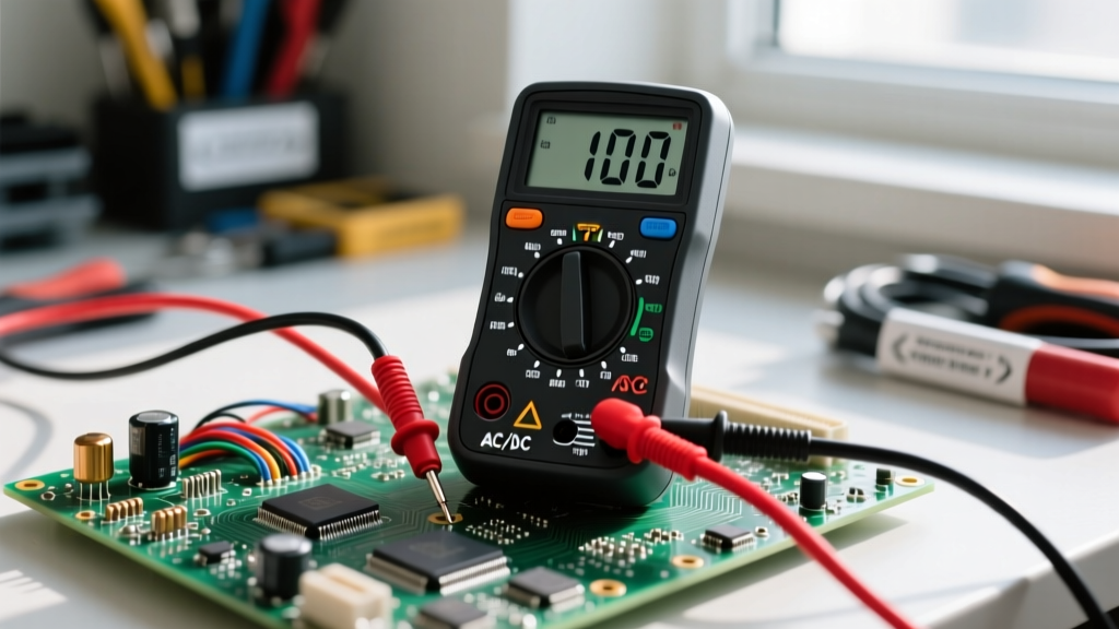
Touch the black probe to the circuit's ground or negative terminal, and the red probe to the positive terminal or test point. If you are testing a PCB, use the fine tips of the probes to avoid bridging adjacent pins, which could short out a sensitive IC.
3. Interpreting the Display
- Positive Reading: The red probe is on the higher potential (positive) side. The circuit is functioning with correct polarity.
- Negative Reading (e.g., -12.05V): The probes are reversed relative to the circuit's polarity. The voltage magnitude is correct, but the red probe is touching the negative side. Swap the probes to verify.
- "OL" or "1" (Overload): The voltage exceeds the selected range on a manual-ranging meter. Turn the dial to a higher voltage setting immediately.
Mains and Appliances: Checking AC Voltage Safely
Measuring AC mains voltage (120V in North America, 230V in Europe) carries a severe shock hazard. According to safety guidelines outlined by Fluke's electrical safety documentation, you must never touch the metal shafts of the probes while testing live AC circuits. Keep your fingers behind the built-in finger guards.
The Three-Point Receptacle Test
To troubleshoot a dead wall outlet, you must perform a three-point test to verify not just the presence of voltage, but the integrity of the grounding system. Set your meter to AC Voltage (V~) and insert the probes into a standard US 120V NEMA 5-15 receptacle as follows:
| Probe Placement | Expected Reading (US) | Diagnostic Meaning |
|---|---|---|
| Hot (Short Slot) to Neutral (Long Slot) | 115V - 125V | Normal circuit operation. Power is reaching the outlet. |
| Hot (Short Slot) to Ground (U-Shape) | 115V - 125V | Confirms the grounding path is intact back to the panel. |
| Neutral (Long Slot) to Ground (U-Shape) | 0V - 2V | Confirms neutral and ground are properly bonded at the panel and not carrying stray load current. |
Troubleshooting Insight: If Hot-to-Neutral reads 120V, but Hot-to-Ground reads 0V, your outlet lacks a functional ground wire. If Neutral-to-Ground reads a high voltage (e.g., 5V to 10V), you likely have a loose neutral connection or an overloaded circuit causing a dangerous voltage drop on the return path.
Understanding Multimeter Safety Categories (CAT Ratings)
Not all multimeters are built to handle the transient voltage spikes found in mains wiring. When troubleshooting AC voltage, your multimeter must have the appropriate CAT (Category) rating. The SparkFun multimeter tutorial emphasizes that a CAT II meter is fine for testing small appliances plugged into a wall, but testing the main service panel or outdoor wiring requires a CAT III or CAT IV meter. A cheap, unrated multimeter can suffer an internal arc explosion if subjected to a lightning-induced transient while measuring mains voltage. Always verify the CAT rating printed near the input jacks before troubleshooting household wiring.
Advanced Troubleshooting: Ghost Voltages and Voltage Drops
Two of the most common phenomena that confuse DIYers and apprentice electricians are ghost voltages and voltage drops. Understanding how to use a multimeter to check voltage in these scenarios separates amateurs from professionals.
Defeating Ghost Voltage
When running long cables in a conduit, an unconnected, dead wire running parallel to a live "hot" wire can act as a capacitor. This induces a "ghost voltage" on the dead wire. A high-impedance digital multimeter (which draws almost zero current) will read this phantom voltage—often showing 40V to 90V on a completely disconnected wire, leading you to believe the circuit is live.
The Fix: Use a multimeter with a Low-Z (Low Impedance) mode, or use an older analog solenoid tester (like a Wiggy). Low-Z mode places a small internal load on the circuit, which instantly dissipates the capacitive ghost voltage, dropping the reading to a true 0V. Advanced troubleshooting guides, such as those found on All About Circuits, highly recommend Low-Z meters for residential HVAC and lighting troubleshooting.
Measuring Voltage Drop (The Live Circuit Test)
A common mistake is using the multimeter's continuity (beep) setting to check a fuse or a switch. Continuity must only be tested on de-energized circuits. To troubleshoot a fuse or switch while the system is powered on, you must measure voltage drop.
Pro Troubleshooting Rule: Place your red probe on the line (input) side of a fuse, and your black probe on the load (output) side. If the fuse is good, the resistance is near zero, and the multimeter will read 0.00V. If the fuse is blown, the multimeter will read the full source voltage (e.g., 12V or 120V), indicating the electrical pressure is blocked at that exact point.
Real-World Diagnostic Scenarios
Scenario 1: The Parasitic Draw in a Vehicle
Your car battery keeps dying overnight. Before testing for current (amps), you must verify the battery's resting voltage. A healthy, fully charged 12V lead-acid battery should read 12.6V to 12.8V with the engine off. If your multimeter reads 11.9V or lower, the battery has a bad cell or is deeply discharged and must be charged before any parasitic draw testing can be accurately performed. Furthermore, check the alternator output by measuring the battery terminals while the engine is running; it should read between 13.7V and 14.4V. Anything higher indicates a failing voltage regulator that will boil the battery acid.
Scenario 2: Dimming LED Strip Lights
You have installed a 5-meter run of 12V LED strip lights, but the end of the strip is noticeably dimmer and shifting from white to yellow. This is a classic voltage drop issue caused by the resistance of the copper traces on the LED strip. Use your multimeter to check the DC voltage at the power supply terminals (it should read exactly 12.0V). Then, carefully touch your probes to the copper pads at the very end of the 5-meter strip. If the multimeter reads 10.5V or lower, the LEDs are starved of power. The troubleshooting solution is to inject power at both ends of the strip or upgrade to a thicker gauge wire for the main feed.
Summary Checklist for Voltage Troubleshooting
Mastering how to use a multimeter to check voltage requires a methodical approach. Always verify your meter's battery (a low DMM battery can cause false, erratic readings). Confirm your probe placement before turning the dial. Respect the CAT ratings when dealing with AC mains, and utilize Low-Z modes to eliminate phantom readings. By treating voltage as a map of electrical pressure, you can isolate faults, identify broken connections, and safely restore power to any circuit.