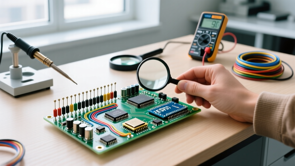

The Hidden Safety Risks of Component Heterogeneity
In high-power and high-reliability electronics, the assumption that identical part numbers yield identical electrical behavior is a dangerous fallacy. When designing parallel power stages, precision analog front-ends, or battery management systems (BMS), the homogeneity in electronic components dictates the difference between a stable circuit and a catastrophic thermal event. Homogeneity refers to the parametric uniformity of components within a single manufacturing batch, encompassing variations in threshold voltages, parasitic inductances, and dielectric consistencies.
According to reliability research from the Center for Advanced Life Cycle Engineering (CALCE), batch-to-batch parametric drift is a leading root cause of early-life failures in power electronics. When engineers or DIY builders mix date codes or source from unverified distributors, they introduce heterogeneity that bypasses standard safety margins.
The Thermal Runaway Cascade: In parallel MOSFET configurations, a gate-to-source threshold voltage (Vgs(th)) mismatch of just 0.2V can cause the lower-threshold device to turn on first and conduct 80% of the load current. Because the Rds(on) temperature coefficient is positive, the hotter device hogs even more current until the silicon die fractures or catches fire.
Sourcing Best Practices: Avoiding the Mixed-Batch Hazard
Achieving component homogeneity begins at the procurement stage. The secondary market is flooded with counterfeit, re-marked, or mixed-lot semiconductors. To maintain safety standards compliant with IPC assembly and reliability guidelines, you must enforce strict lot-tracking protocols.
Lot Code Verification Matrix
| Sourcing Channel | Date Code Consistency | Parametric Spread Risk | Safety Verdict |
|---|---|---|---|
| Franchised Distributors (e.g., Digi-Key, Mouser) | Single Lot / Reel | Extremely Low | Mandatory for life-safety & high-power |
| Authorized Broker Networks | Mixed Lots (Verify D/C) | Low to Moderate | Acceptable if bench-tested before deployment |
| Direct Import Marketplaces (e.g., AliExpress) | Highly Variable / Re-marked | Severe | Unsafe for parallel power stages or precision BMS |
| Surplus / Liquidation Sellers | Unknown / Degraded | Critical | Avoid entirely for any safety-critical application |
Bench Testing Protocols for Parametric Matching
Even when sourced from franchised distributors, high-power semiconductors like IGBTs or SiC MOSFETs require bench matching before being paralleled. Relying on cheap $25 multi-testers (like the ubiquitous TC1 transistor checker) is a severe safety risk; these devices test Vgs(th) at micro-amp levels, entirely missing the high-current thermal characteristics required for real-world matching.
Step-by-Step High-Current Matching Procedure
- Thermal Stabilization: Mount the components (e.g., Infineon IRFP460 MOSFETs) to a shared, temperature-controlled heatsink using a uniform torque of 0.5 Nm to ensure identical thermal interface resistance.
- Curve Tracing: Use a dedicated curve tracer (such as a used Tektronix 370A, approx. $800 on the secondary market, or a modern Keysight B1505A for professional labs) to plot the Id vs. Vgs transfer characteristics at the actual operating junction temperature (typically 80°C to 100°C).
- Current Hogging Test: Inject a continuous DC current using an electronic load (e.g., BK Precision 8500B, ~$400) set to your circuit's maximum continuous rating. Monitor individual branch currents using a Hall-effect clamp meter (e.g., Fluke 376 FC).
- Binning: Group components that exhibit less than a 5% current deviation at full load. Discard or repurpose outliers for single-ended, low-power circuits.
Passive Component Homogeneity: The MLCC Trap
Heterogeneity is not limited to active semiconductors. Multi-Layer Ceramic Capacitors (MLCCs) are notorious for batch variations, particularly regarding DC bias characteristics. A 10µF X7R capacitor from Batch A might retain 6µF under a 12V DC bias, while a visually identical 10µF X5R capacitor from Batch B might drop to 1.5µF under the same conditions.
The Safety Consequence: In a switching power supply output filter, mixing these batches results in unpredictable voltage ripple. If the ripple exceeds the tolerance of the downstream microcontroller's brown-out detector (BOD), the system can experience erratic resets, leading to uncontrolled relay states or motor drive failures. Always procure MLCCs from a single, continuous tape-and-reel for critical decoupling networks, and verify the manufacturer's DC bias simulation models (e.g., Murata's SimSurfing tool) before finalizing the BOM.
Mitigation: Designing Failsafes Against Heterogeneity
When absolute homogeneity cannot be guaranteed, circuit topology must compensate. The NASA Electronic Parts and Packaging (NEPP) program heavily advocates for design-level derating and ballasting in high-reliability aerospace applications to mitigate component mismatch.
Calculating Source/Emitter Ballast Resistors
To force current sharing in parallel MOSFETs, insert low-value ballast resistors in the source path. This introduces negative feedback: as one MOSFET heats up and its Rds(on) increases, the voltage drop across its ballast resistor reduces the effective Vgs, naturally throttling the current.
- Target Voltage Drop: Aim for a 100mV to 200mV drop across the resistor at nominal current to overpower the Vgs(th) mismatch.
- Example Calculation: For a 20A total load shared by two MOSFETs (10A each), a 0.015Ω resistor yields a 150mV drop (0.015Ω × 10A = 0.15V).
- Power Rating & Derating: Power dissipation is I²R = 10² × 0.015 = 1.5W. For safety, apply a 50% derating rule and select a 3W or 5W chassis-mount resistor (e.g., Dale RH-5, approx. $4.50 each) bolted directly to the main heatsink.
FAQ: Troubleshooting Homogeneity Failures
Why did my parallel Li-ion battery pack fail despite using the same model cells?
Even genuine cells (e.g., Samsung 30Q) from different production months exhibit internal resistance (IR) variances of 10-15mΩ. In high-discharge scenarios, the lower-IR cell delivers disproportionate current, aging faster and eventually venting. Always match cells by measuring AC impedance at 1kHz using a dedicated internal resistance meter (e.g., Hioki BT3554), grouping cells within a 2mΩ spread.
Can I mix op-amps from different manufacturers if the part number is the same?
No. A generic 'LM358' from Texas Instruments, STMicroelectronics, and a secondary fab will have different input offset voltages, slew rates, and crossover distortion profiles. In precision sensor amplification, this heterogeneity introduces unpredictable DC offsets and stability issues. Always lock your BOM to a specific manufacturer's suffix.
How does PCB layout affect thermal homogeneity?
Asymmetrical copper pours create thermal gradients. If one parallel component is closer to a thermal via array or a board edge, it will run cooler, altering its parametric behavior compared to its hotter counterpart. Use symmetrical, star-routed power traces and uniform thermal via stitching (e.g., 0.3mm vias on a 1.0mm grid) under all parallel power devices to ensure identical thermal boundary conditions.