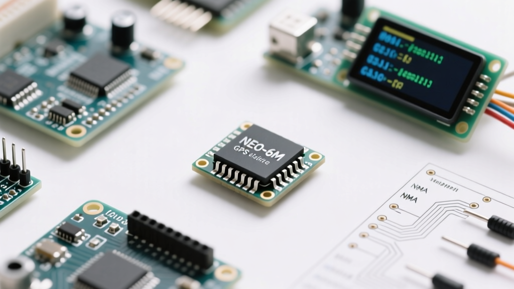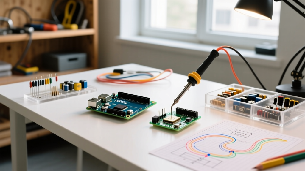

The Skill-Building Path to Component Mastery
While searching for an all electronic components list with images is the standard first step for beginners, true mastery requires moving beyond simple visual identification. To transition from a novice who merely copies schematics to a competent engineer who designs and troubleshoots circuits, you must understand the physical realities, failure modes, and modern part numbers of every component on your workbench.
In 2026, the barrier to entry for electronics is lower than ever, with comprehensive through-hole and SMD (Surface Mount Device) starter kits available for $25 to $45. However, having the parts is only 10% of the battle. This guide is structured as a progressive skill-building path, taking you from passive foundations to complex integrated circuits, complete with real-world part numbers and critical engineering insights.
Phase 1: The Passive Foundation
Passive components cannot amplify signals or control current flow actively, but they form the bedrock of every circuit. Understanding their non-ideal characteristics is what separates hobbyists from professionals.
Resistors: Beyond the Color Code
Beginners often view resistors solely as current limiters defined by their ohmic value. However, in practical 2026 circuit design, tolerance, temperature coefficient (TCR), and parasitic inductance matter immensely.
- Standard Hobbyist Part: 1/4W 1% Metal Film Resistor Assortment (Typical cost: $14 for 600+ values).
- Visual ID: Cylindrical body with blue or tan coating, distinct color bands. Wire leads are copper-clad steel.
- Pro Insight: Avoid carbon composition resistors for audio or precision analog circuits; they generate significant thermal noise. Always specify metal film.
- Failure Mode: Thermal runaway. If a 1/4W resistor dissipates 0.3W in a poorly ventilated enclosure, its resistance will drift due to a positive temperature coefficient, eventually leading to an open circuit or charring.
Capacitors: Dielectrics and ESR
Capacitors store energy in an electric field. The visual difference between a ceramic disc and an aluminum electrolytic is obvious, but the hidden parameter—Equivalent Series Resistance (ESR)—dictates their real-world utility.
For a deep dive into how capacitors behave in real circuits, refer to SparkFun's comprehensive capacitor tutorial, which breaks down the physics of charge storage.
| Capacitor Type | Visual Identification | Best Application | Critical 2026 Selection Metric |
|---|---|---|---|
| MLCC (Ceramic) | Tiny, flat, usually brown/yellow. No polarity. | High-frequency decoupling, bypassing. | Use X7R dielectric over Y5V. Y5V loses up to 80% capacitance under DC bias voltage. |
| Aluminum Electrolytic | Cylindrical can, silver/black. Stripe denotes negative. | Bulk power supply filtering, audio coupling. | Check ESR rating. Low-ESR types (e.g., Panasonic FR series) are mandatory for switching power supplies. |
| Tantalum | Small, teardrop-shaped, often yellow or black. Band is positive. | Space-constrained low-frequency filtering. | Highly sensitive to reverse voltage and current spikes. Can fail catastrophically (ignite) if derated poorly. |
Phase 2: Active & Semiconductor Control
Active components allow a small signal to control a much larger current, enabling amplification and switching. This is where the skill-building path demands a solid grasp of semiconductor physics.
Diodes: One-Way Streets and Voltage Clamps
A diode allows current to flow in one direction while blocking it in the other. But not all diodes are created equal.
- Standard Rectifier (1N4007): Visually identified by a black cylinder with a single silver band (cathode). Handles up to 1A and 1000V reverse voltage, but has a slow reverse recovery time. Useless for high-frequency switching.
- Schottky Diode (1N5819): Similar visual profile but typically features a more pronounced, sometimes metallic band. Offers a low forward voltage drop (~0.2V vs 0.7V for silicon) and ultra-fast switching. Essential for modern buck converters.
- Zener Diode (BZX55C5V1): Designed to operate in the reverse breakdown region. Visually, they often look like standard signal diodes but are color-coded or marked with their breakdown voltage. Used for crude voltage regulation and overvoltage clamping.
Transistors: The Building Blocks of Logic
Transistors act as electrically controlled switches or amplifiers. Understanding the transition from Bipolar Junction Transistors (BJTs) to Metal-Oxide-Semiconductor Field-Effect Transistors (MOSFETs) is a major milestone in your skill path.
Expert Warning on MOSFET Gate Sensitivity: The gate of a MOSFET like the popular IRLZ44N (a logic-level N-channel MOSFET in a TO-220 package) is essentially a capacitor separated by an incredibly thin layer of silicon dioxide. A static shock from your finger (often exceeding 2,000V) can instantly puncture this gate oxide, destroying the component silently. Always store MOSFETs in anti-static bags and use ESD-safe mats when handling them.
For a rigorous academic foundation on how these semiconductor junctions actually function at the atomic level, the All About Circuits textbook on semiconductors remains an unparalleled free resource for self-taught engineers.
Phase 3: Integrated Circuits (ICs) & Microcontrollers
ICs package hundreds to billions of transistors into a single, easy-to-use black epoxy block. The skill here lies in reading datasheets and understanding peripheral requirements.
Linear vs. Switching Voltage Regulators
Power management is often the first hurdle in a DIY project. You must know when to use linear regulators and when to step up to switching topologies.
- The Classic Linear Regulator (LM7805): A 3-pin TO-220 package. It drops 12V down to 5V by burning the excess 7V as pure heat. At 1A of current, it dissipates 7 Watts—requiring a massive heatsink. It is simple, low-noise, but highly inefficient.
- The Modern Buck Converter (LM2596 Module): Typically sold as a small PCB with an inductor, Schottky diode, and electrolytic capacitors. It steps down voltage using high-frequency switching, achieving 85%+ efficiency. It runs cool but introduces switching noise into the circuit.
Microcontrollers: The Brains
In 2026, the microcontroller landscape is dominated by connectivity and edge-AI capabilities.
- ATmega328P (The Arduino Core): A 28-pin DIP chip. 8-bit architecture, 32KB Flash. Perfect for learning basic I/O, timers, and interrupts. Still widely available in through-hole format for breadboarding.
- ESP32-WROOM-32E: A surface-mount module usually broken out onto a development board. Dual-core 32-bit Xtensa processor running at 240MHz, with integrated Wi-Fi and Bluetooth 5.0. It requires an understanding of RTOS (Real-Time Operating Systems) and memory management, representing a steep but necessary step up the skill-building path.
Phase 4: Electromechanical & Interconnects
The physical world meets the digital world through electromechanical components. These parts suffer from mechanical wear, contact bounce, and inductive kickback.
Relays and the Flyback Diode
A standard 5V SPDT relay (like the Omron G5V-2) uses a small electromagnet to physically move metal contacts, allowing a 3.3V microcontroller pin to switch a 120V AC mains load or a 12V DC motor.
Critical Failure Mode: When the relay coil is de-energized, the collapsing magnetic field generates a massive reverse voltage spike (inductive kickback) that will instantly fry your driving transistor or microcontroller. You must always place a flyback diode (e.g., 1N4148) in reverse bias across the relay coil to safely recirculate this energy.
Switches and Contact Bounce
Mechanical tactile switches do not make a clean electrical connection. When pressed, the metal contacts physically bounce against each other for 1 to 10 milliseconds before settling. To a microcontroller executing millions of instructions per second, one button press looks like 50 rapid presses. Mastering hardware debouncing (using an RC low-pass filter) or software debouncing (using state-machine timers) is a mandatory rite of passage. For practical implementation strategies, review SparkFun's guide on pull-up resistors and switch interfacing.
Actionable Skill-Building Exercise: The Component Sorting Protocol
Before you solder a single joint, you must master inventory management. A disorganized workbench leads to lost time and accidental short circuits.
- Invest in ESD-Safe Storage: Buy a 64-compartment plastic tackle box with adjustable dividers. Line the bottom with anti-static foam for sensitive ICs and MOSFETs.
- Labeling Standard: Do not rely on memory. Use a label maker to tag every bin. Include the component value, the part number (e.g., '10k 1/4W MF'), and the bin location code.
- Scrap Wire Management: Keep three separate bins for stripped solid-core jumper wires sorted by length: short (1 inch), medium (3 inches), and long (6 inches). This prevents the 'spaghetti wire' mess that plagues beginner breadboards.
Conclusion: Moving From Identification to Intuition
Having an all electronic components list with images is merely your map; the territory is explored through deliberate practice. Your next step on this skill-building path is to take the specific part numbers listed above—like the IRLZ44N MOSFET, the X7R ceramic capacitors, and the LM2596 buck converter—and design a custom, variable-speed DC motor controller on a breadboard. Measure the heat, observe the waveforms on an oscilloscope, and intentionally push the components to their limits (safely) to understand their failure modes. That is how you transition from reading about electronics to truly engineering them.