
The Skill-Building Path to Component Mastery
Transitioning from a beginner who merely copies schematics to an intermediate designer who intuitively selects parts requires a fundamental shift in perspective. Memorizing datasheets is not enough; you must understand how different electronic components behave under real-world stress, temperature variations, and parasitic effects. This guide outlines a progressive skill-building path, moving from passive foundations to active switching and integrated power management, equipping you with the exact specifications, failure modes, and selection frameworks used by professional hardware engineers in 2026.
Phase 1: The Passive Foundation (Beginner to Intermediate)
Passive components do not amplify signals, but they dictate the stability, noise floor, and timing of your entire circuit. The most common beginner mistake is treating passives as ideal, mathematically perfect parts.
Resistors: Beyond the Color Code
While a 10kΩ resistor limits current, its physical construction dictates its reliability. For through-hole prototyping, 1/4W carbon film resistors are standard. However, for surface-mount device (SMD) PCB design, you will use thick-film chip resistors like the Yageo RC0805 series. Pro Tip: Always check the Temperature Coefficient of Resistance (TCR). A standard 1% thick-film resistor might have a TCR of ±100 ppm/°C, meaning its resistance will drift significantly in high-heat environments. For precision analog front-ends (like load cell amplifiers), you must specify thin-film resistors with a TCR of ±10 ppm/°C.
Capacitors and the DC Bias Trap
Capacitors store energy and filter noise, but Multi-Layer Ceramic Capacitors (MLCCs) suffer from a phenomenon called DC bias derating. If you place a 10µF, 16V X5R ceramic capacitor (such as the Murata GRM21BR61C106KE15) on a 12V power rail, it will not provide 10µF. Due to the piezoelectric properties of the barium titanate dielectric, its actual capacitance can drop to less than 2µF at 12V. To ensure stable power delivery, always select MLCCs with a voltage rating at least 2x to 3x your maximum operating voltage, or use higher dielectric grades like X7R. For deeper insights into dielectric behaviors, consult SparkFun's comprehensive capacitor guide.
Industry Rule of Thumb: Always derate aluminum electrolytic capacitors by 20% for voltage and 10°C for temperature. Every 10°C drop in operating temperature effectively doubles the expected operational lifespan of the capacitor.
Phase 2: Active Control and Switching (Intermediate)
Active components allow a small signal to control a much larger current. Mastering the transition from Bipolar Junction Transistors (BJTs) to Metal-Oxide-Semiconductor Field-Effect Transistors (MOSFETs) is a critical milestone in understanding how different electronic components interface with microcontrollers.
The Logic-Level MOSFET Imperative
Beginners often reach for the IRF520 MOSFET to switch high-current loads like motors or LED strips with an Arduino. This is a critical error. The IRF520 is a standard-level MOSFET requiring a Gate-to-Source voltage (Vgs) of 10V to fully enhance its channel and achieve its rated low on-resistance. When driven by a 5V GPIO pin, it operates in the linear (ohmic) region, acting as a high-value resistor. It will overheat and fail, potentially destroying your microcontroller.
The Solution: Use a true logic-level MOSFET like the IRLZ44N. The IRLZ44N is specifically characterized to provide an Rds(on) of just 22mΩ at Vgs = 5V, allowing it to switch up to 20A with minimal heat dissipation when driven directly from a 5V logic pin. For a detailed breakdown of gate threshold voltages and motor control topologies, refer to this practical tutorial on MOSFET motor control.
BJTs for Signal Amplification
While MOSFETs dominate power switching, BJTs like the ubiquitous 2N3904 (NPN) and 2N3906 (PNP) remain superior for small-signal amplification and high-frequency switching due to their higher transconductance and lower noise profiles. When designing a BJT switch, always calculate the base resistor to force the transistor into deep saturation (typically assuming a forced Beta/hFE of 10, rather than the datasheet's linear hFE of 100+).
Phase 3: Integrated Circuits and Power Management (Advanced)
Integrated Circuits (ICs) package dozens to billions of transistors into a single footprint. In the skill-building path, mastering power regulation is paramount, as poor power delivery causes erratic microcontroller resets and noisy sensor readings.
Linear vs. Switching Regulators
The LM7805 linear regulator is a rite of passage, but it is highly inefficient for high-current or high-differential voltage applications. Dropping 12V to 5V at 1A using an LM7805 results in 7W of dissipated heat (P = (12V - 5V) * 1A), requiring a massive heatsink and triggering the IC's internal thermal shutdown (typically at 150°C junction temperature).
For modern 2026 designs, transition to synchronous buck converters like the Texas Instruments TPS5430 or the AMS1117 (for low-current, low-dropout linear needs). Switching regulators use an internal MOSFET to rapidly chop the input voltage, storing energy in an inductor and smoothing it with a capacitor. This achieves >90% efficiency, meaning that same 12V-to-5V conversion at 1A dissipates less than 0.5W of heat.
Component Selection and Failure Matrix
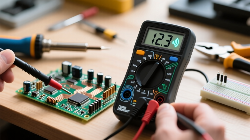
To accelerate your diagnostic skills, use this matrix to understand how different electronic components fail in the field and how to test them.
| Component Class | Common Real-World Failure Mode | Multimeter Diagnostic Setting | Prevention Strategy |
|---|---|---|---|
| MLCC Capacitor | Mechanical cracking from PCB flexure, leading to short circuits. | Continuity / Resistance (Look for near 0Ω across rails). | Keep large MLCCs away from board edges and V-score lines. |
| Electrolytic Capacitor | Electrolyte boil-off due to high ESR and ripple current heating. | ESR Meter (Measure Equivalent Series Resistance in-circuit). | Use 105°C rated low-ESR caps (e.g., Panasonic FR series) for switching supplies. |
| MOSFET | Gate oxide puncture from Electrostatic Discharge (ESD). | Diode Test Mode (Check body diode and gate isolation). | Include a 10kΩ pull-down on the gate and a 15V Zener diode for clamping. |
| Schottky Diode | Thermal runaway due to high reverse leakage current at elevated temps. | Diode Test Mode (Expect 0.2V - 0.4V forward drop). | Derate reverse voltage by 50% in high-temperature environments. |
Edge Cases: Parasitics and PCB Layout
As you advance, you must realize that every physical component introduces parasitic inductance and capacitance. A simple 0805 resistor has a parasitic series inductance of roughly 0.5nH. At DC, this is irrelevant. But in a 2.4GHz RF circuit (like an ESP32-S3 antenna trace), that parasitic inductance will severely detune your impedance matching network.
Furthermore, solder joint reliability is governed by standards like IPC-A-610. A component that is perfectly functional on the bench may fail in a vibrating automotive environment if the solder fillet lacks proper wetting or if the component leads experience mechanical fatigue. Always use appropriate strain relief for heavy through-hole components and ensure your PCB footprint pads match the manufacturer's recommended land patterns exactly.
Next Steps in Your Electronics Journey
Mastering different electronic components is not a destination, but a continuous loop of design, testing, and failure analysis. Your next step should be to acquire a basic digital storage oscilloscope (DSO), such as the Rigol DS1054Z or a modern equivalent, to visualize the switching noise and transient responses that multimeters simply cannot capture. By combining theoretical knowledge of parasitics with empirical bench testing, you will transition from a hobbyist assembling kits to a capable electronics designer ready to tackle complex, mixed-signal systems.