
Why Through Hole Electronic Components Still Matter in 2026
While Surface Mount Technology (SMT) dominates mass-manufactured consumer electronics, through hole electronic components remain the undisputed king of DIY prototyping, aerospace, and high-power industrial applications. For beginners, learning to solder through hole technology (THT) builds the foundational thermal and mechanical intuition required for all electronics work. Unlike SMT, which requires specialized stencils, reflow ovens, and microscopes, THT allows you to build robust, repairable circuits on a standard workbench with minimal capital investment.
In this comprehensive tutorial, we will bypass generic advice and dive into the exact metallurgy, tool specifications, and thermal timing required to produce IPC-compliant solder joints on through hole components.
The Mechanical Advantage of THT
Through hole components feature long wire leads that pass completely through the printed circuit board (PCB) and are soldered to the opposite side. This creates a mechanical bond that is exponentially stronger than the surface-level adhesion of SMT pads. This is why heavy components like large electrolytic capacitors, high-wattage resistors, and board-mounted connectors still rely on through hole electronic components in modern power supply designs.
Anatomy of Through Hole Electronic Components
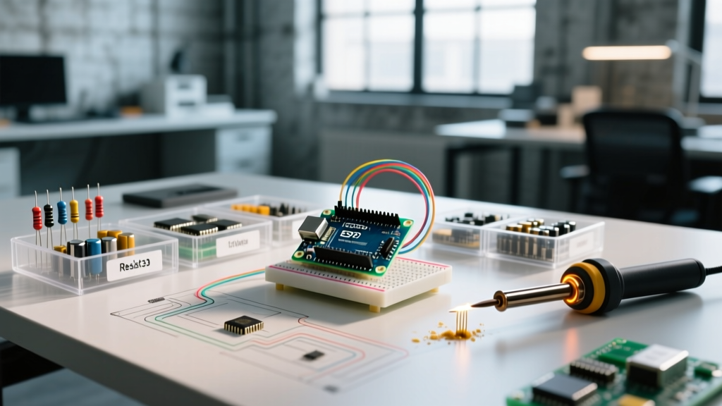
Before applying heat, you must understand the physical dimensions of the components you are working with. The industry standard grid for through hole prototyping is 0.1 inch (2.54mm). However, lead spacing varies heavily depending on the component's power rating and physical size.
| Component Type | Standard Lead Pitch | Example Model | Primary Application |
|---|---|---|---|
| 1/4W Carbon Film Resistor | 0.4" (10.16mm) | Yageo CFR-25 | Current limiting, pull-ups |
| Electrolytic Capacitor | 0.1" to 0.2" (2.54-5.08mm) | Panasonic FR Series | Bulk power filtering |
| DIP Integrated Circuit | 0.1" (2.54mm) grid | TI NE555P | Logic, timers, microcontrollers |
| TO-220 MOSFET / Regulator | 0.1" spacing (3-pin) | Infineon IRF520 | High-power switching, voltage regulation |
| 5mm Standard LED | 0.1" (2.54mm) | Lite-On LTL-307EE | Status indication |
The 2026 Beginner Workbench Setup
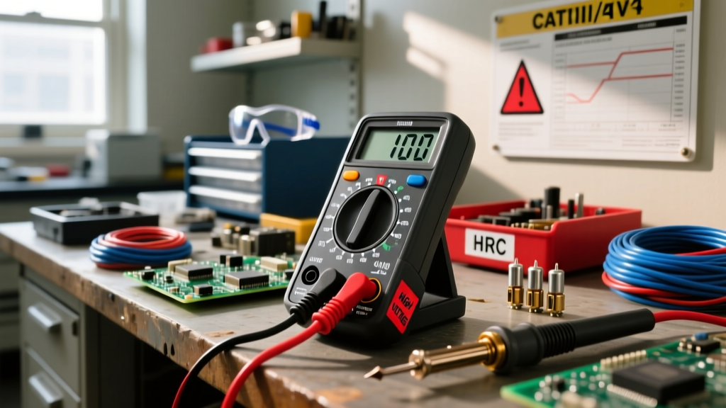
To successfully solder through hole electronic components, you need tools that offer precise thermal recovery. Cheap 30W plug-in irons will fail when soldering to large ground planes, resulting in cold joints. Here is the exact bill of materials for a professional-grade beginner bench (Total Cost: ~$150).
- Soldering Station: Hakko FX-888D or Weller WLC100 (~$110). These stations feature active thermal sensors in the tip, allowing them to recover heat instantly when touching a cold copper pad.
- Solder Alloy: Kester 245 63/37 Leaded Rosin Core, 0.031" diameter (~$14). The 63/37 ratio is eutectic, meaning it transitions instantly from solid to liquid at 183°C (361°F) without a plastic (semi-solid) phase. This is critical for beginners to avoid disturbing joints during cooling.
- Tip Selection: Use a 1.2mm Chisel tip (Hakko T18-D12). Avoid conical (pencil) tips; a chisel tip maximizes surface area contact between the round component lead and the flat PCB pad.
- Flux: MG Chemicals 8350N No-Clean Liquid Flux (~$9). Flux dissolves copper oxide, allowing the molten solder to metallurgically bond to the metal rather than just sitting on top of it.
- Desoldering Braid: Chemtronics 25-736-3 (~$8). Essential for removing mistakes and clearing solder bridges.
The 4-Step Soldering Sequence
According to the IPC J-STD-001 standard for soldered electrical assemblies, a proper solder joint requires specific wetting angles and thermal profiles. Follow this exact sequence for every pin.
- Mechanical Preparation: Insert the component lead through the PCB hole. Bend the lead outward at a 45-degree angle using needle-nose pliers. This secures the component mechanically so it won't fall out when you flip the board, and it increases the thermal mass contact area.
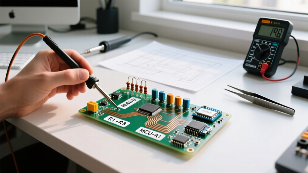
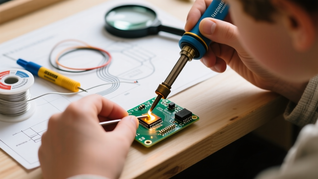
- The Thermal Bridge (3 Seconds): Set your station to 350°C (662°F) for leaded solder. Clean the iron tip on a brass wire sponge, then apply a tiny amount of solder to the tip (tinning). Place the flat side of the chisel tip so it touches both the component lead and the copper pad simultaneously. Hold for exactly 2 to 3 seconds to raise the local temperature above the solder's melting point.
- Feed the Solder: Remove the solder wire from its spool and touch it to the opposite side of the joint, not directly to the iron tip. If the pad and lead are hot enough, the flux will activate (smoke lightly) and the solder will wick smoothly around the base of the lead via capillary action. Feed exactly 1/4 inch of solder wire for a standard 0.1" pad.
- The Withdrawal: Remove the solder wire first, wait one half-second to let the fillet settle, then remove the iron tip in a swift, upward motion. Do not blow on the joint or move the board for at least 5 seconds. Moving a eutectic joint while it crosses the 183°C threshold will cause microscopic fractures known as a 'disturbed joint'.
Troubleshooting: Identifying Bad Joints
Even experienced engineers encounter anomalies when soldering through hole electronic components. Here is how to diagnose and fix the three most common failure modes.
The Cold Joint: The solder looks dull, grainy, and forms a bulbous sphere instead of a smooth concave fillet.
Cause: Insufficient heat transfer. The iron was removed too early, or the pad was connected to a massive ground plane that acted as a heatsink.
Fix: Apply a drop of liquid flux to the joint. Reapply the iron for 4-5 seconds, feed a tiny amount of fresh solder to introduce new flux core, and withdraw.
Solder Bridges (Short Circuits)
When soldering tightly spaced DIP ICs (0.1" pitch), solder can easily flow between adjacent pads, creating a dead short.
The Fix: Do not use a solder sucker, which can rip the copper pad off the fiberglass substrate. Instead, place a piece of Chemtronics desoldering braid over the bridge, press your hot chisel tip directly onto the braid, and drag it slowly across the pins. The copper braid will absorb the excess solder via capillary action, leaving perfectly separated pins. As noted in the SparkFun soldering tutorial, always clean the area with isopropyl alcohol afterward to remove the corrosive flux residue.
Lifted Pads
If you apply heat for longer than 6-8 seconds, the epoxy resin holding the copper pad to the FR4 fiberglass can delaminate, causing the pad to lift off the board.
The Fix: Stop heating immediately. If the pad is completely detached, use 30 AWG Kynar wire-wrap wire to route a physical connection from the component lead to the next available via or trace on the PCB.
THT vs. Surface Mount: When to Choose Which?
As you progress in your electronics journey, you will inevitably encounter SMT. Here is a quick decision matrix to help you choose the right footprint for your 2026 projects:
| Design Requirement | Through Hole (THT) | Surface Mount (SMT) |
|---|---|---|
| Mechanical Stress | Excellent (Connectors, heavy relays) | Poor (Requires mechanical reinforcement) |
| High Voltage / Creepage | Excellent (Wide physical spacing) | Requires specialized slot-routing in PCB |
| Prototyping Speed | Fast (No stencils or hot air required) | Slow (Requires breakout boards or microscopes) |
| High-Frequency RF | Poor (Long leads create parasitic inductance) | Excellent (Minimal lead length) |
| Automated Assembly | Expensive (Requires wave soldering machines) | Cheap (Pick-and-place + reflow oven) |
Final Workbench Safety & Maintenance
Proper maintenance of your tools ensures consistent results when working with through hole electronic components. Always keep your iron tip tinned with a thick layer of solder when powering down. This sacrificial layer prevents the iron plating from oxidizing in the air, which would render the tip useless and unable to transfer heat. Furthermore, ensure your workspace is ventilated. While modern no-clean fluxes are less toxic than traditional rosin, the Adafruit Guide to Excellent Soldering strongly recommends using a fume extractor or a simple desk fan to push particulate matter away from your breathing zone.
By mastering the thermal dynamics and mechanical prep of through hole components, you establish a baseline of craftsmanship that will translate to every other area of electrical engineering, from high-voltage wiring to microscopic SMT rework.