
The Modern Vehicle: A Rolling Network of Electronic Components
Modern vehicles are no longer purely mechanical machines; they are highly complex, rolling data centers. A typical late-model passenger vehicle contains between 70 and 150 distinct Electronic Control Units (ECUs) managing everything from powertrain timing to seat memory. For the DIY enthusiast or aspiring technician, understanding automotive electronic components is no longer optional—it is the fundamental baseline of modern repair.
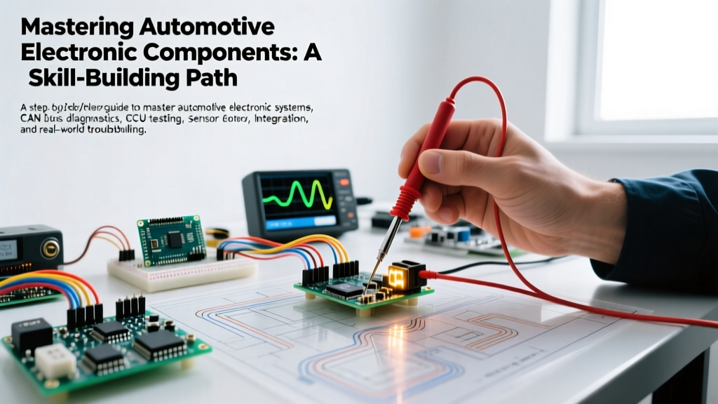
This guide provides a structured, three-phase skill-building path designed to take you from basic multimeter checks to advanced CAN bus network diagnostics. By following this progression, you will develop the diagnostic intuition required to tackle intermittent electrical faults, sensor failures, and module communication errors.
Phase 1: Foundational Diagnostics (Beginner)
Before attempting to diagnose complex data networks, you must master the absolute basics of automotive circuits: power, ground, and load. The most common failure points in automotive electronic components are not the microchips themselves, but the wiring harnesses, connectors, and grounds that supply them.
Essential Beginner Tool Kit
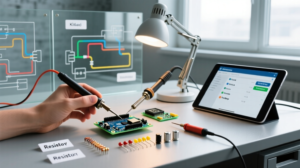
As of 2026, entry-level diagnostic tools have become highly capable and affordable. Here is the baseline kit required for Phase 1:
| Tool Type | Recommended Model | Approx. Cost (2026) | Primary Use Case |
|---|---|---|---|
| Digital Multimeter (DMM) | Fluke 115 or Fluke 88V (Automotive) | $200 - $450 | Voltage drop, resistance, continuity |
| Circuit Tester / Power Probe | Power Probe IV | $250 | Applying power/ground, testing relays |
| OBD2 Code Reader | Ancel AD310 or Topdon ArtiLink | $35 - $60 | Retrieving generic P-codes and freeze frame data |
The Voltage Drop Test: Your Most Critical Skill
Beginners often test for battery voltage (12.6V) at a component and assume the circuit is healthy. This is a critical error. A single strand of copper wire can carry 12V but fail to deliver the amperage required to operate a fuel pump or ECU. Voltage drop testing measures the exact amount of voltage consumed by the wiring and connectors under load.
- Procedure: Set your DMM to DC Volts. Connect the red lead to the battery positive terminal and the black lead to the power pin at the component connector (with the circuit turned ON and under load).
- Specification: A healthy power circuit should drop no more than 0.1V per connection and no more than 0.2V total from the battery to the load.
- Ground Side: Repeat from the battery negative terminal to the component ground pin. Maximum acceptable drop is 0.1V total.
Phase 2: Intermediate Circuit & Sensor Analysis
Once power and ground are verified, the next phase of mastering automotive electronic components involves testing the sensors and actuators that communicate with the ECU. This requires moving beyond simple DC voltage checks and understanding signal generation.
Variable Reluctance (VR) vs. Hall Effect Sensors
Camshaft and crankshaft position sensors generally fall into two categories, and misidentifying them is a common diagnostic trap.
Expert Insight: Never apply external voltage to a Variable Reluctance (VR) sensor. VR sensors are passive magnetic generators that produce an AC sine wave. Their amplitude and frequency increase with engine RPM. Conversely, Hall Effect sensors are active; they require a 5V or 12V reference voltage from the ECU and output a digital square wave by pulling the signal to ground.
Step-by-Step: Testing an Alternator Diode Trio
Failing automotive electronic components often manifest as secondary symptoms. A failing alternator diode trio will cause AC current to leak into the vehicle's DC electrical system, leading to flickering lights, erratic ECU behavior, and premature battery failure.
- Start the engine and turn on high-draw accessories (headlights, blower motor on high) to load the alternator.
- Set your DMM to AC Volts.
- Place the probes directly on the battery positive and negative posts.
- Analysis: A healthy alternator should show an AC ripple of less than 50mV (0.050V). If your reading exceeds 100mV, the internal diode rectifier assembly has failed, allowing AC current to contaminate the DC network.
Phase 3: Advanced CAN Bus & Network Troubleshooting
The Controller Area Network (CAN bus) is the central nervous system of modern vehicles. When multiple unrelated automotive electronic components fail simultaneously, or the dash lights up like a Christmas tree, you are likely dealing with a network fault, not individual component failures.
Understanding CAN Bus Topography
The CAN network relies on a twisted pair of wires: CAN High (CAN H) and CAN Low (CAN L). These wires carry differential signals that cancel out electromagnetic interference (EMI). To diagnose network faults, you must understand the physical layer specifications.
CAN Bus Quick-Reference Matrix (OBD2 Pins 6 & 14)
- CAN High (Pin 6): Recessive 2.5V | Dominant 3.5V
- CAN Low (Pin 14): Recessive 2.5V | Dominant 1.5V
- Terminating Resistors: Two 120-ohm resistors in parallel = 60 ohms total (measured with battery disconnected).
- Short to Ground: Network crashes, U-codes (U0100, U0401) populate across multiple modules.
Advanced Tooling: The Automotive Oscilloscope
While a DMM can measure the average voltage of a CAN bus, it cannot decode the high-speed digital square waves operating at up to 500 kbps. For advanced diagnostics, an automotive oscilloscope is mandatory. According to Pico Technology, a leading manufacturer of automotive scopes, visualizing the physical layer of the CAN bus allows technicians to spot voltage spikes, skewed bit timing, and degraded wiring that a multimeter will completely miss.
As of 2026, the PicoScope 4425A (retailing around $1,350) remains the industry gold standard for DIYers and professionals alike, offering 200V input protection and built-in serial decoding for CAN, LIN, and FlexRay networks.
Common Failure Modes in Automotive Electronic Components
Understanding how and why specific components fail accelerates your diagnostic path. Below is a matrix of common edge cases and their diagnostic signatures.
| Component | Common Failure Mode | Diagnostic Symptom / Edge Case | Estimated Repair Cost |
|---|---|---|---|
| Mass Air Flow (MAF) Sensor | Hotwire contamination from oiled air filters | Long Term Fuel Trim (LTFT) +15% at idle; MAF reading lower than calculated load. | $85 - $250 (Sensor replacement) |
| Oxygen (O2) Sensor Heater | Internal heating element open circuit | P0135/P0141 codes. Sensor reads a lazy, flat line until exhaust gas naturally heats it. | $40 - $120 (Sensor replacement) |
| CAN Bus Wiring Harness | Chafing near firewall grommets or steering column | Intermittent U-codes that only appear when the steering wheel is turned or doors are closed. | $150 - $600 (Harness repair) |
| Ignition Coil (COP) | Internal epoxy breakdown under thermal load | Misfires (P030X) that only occur at operating temp or under heavy boost/load; ohms test normal when cold. | $45 - $110 (Per coil) |
Safety Warning: The High-Voltage Frontier
As hybrid and electric vehicles (EVs) dominate the 2026 market landscape, the skill-building path for automotive electronic components must now include High-Voltage (HV) safety. Never probe, cut, or disconnect orange-cabled wiring. These cables carry anywhere from 400V to 800V DC. A puncture to the skin or a dropped tool across an HV busbar can be instantly fatal. Always use Category III or IV rated test leads (like the Fluke TL885) and complete proper EV depowering procedures before working near the inverter or battery management system (BMS).
Building Your Diagnostic Arsenal & Next Steps
Mastering automotive electronic components is a journey of continuous learning. To formalize your skills and access advanced diagnostic case studies, leverage the following industry resources:
- ASE Certification: Pursue the ASE L1 (Advanced Engine Performance) and L2 (Advanced Electrical/Electronic Systems) certifications. The study guides alone are invaluable for understanding OEM diagnostic trees.
- iATN Network: Join the International Automotive Technicians Network. It is the largest global repository of real-world, peer-reviewed diagnostic fixes and waveform captures.
- OEM Wiring Diagrams: Invest in a subscription to ALLDATA DIY or Mitchell1 ProDemand. Guessing wire colors or pinouts in modern vehicles will lead to blown ECUs; always verify against factory schematics.
By systematically building your skills from basic voltage drops to advanced oscilloscope network analysis, you will transition from simply swapping parts based on OBD2 codes to accurately diagnosing the root cause of complex automotive electronic failures.