
The Ultimate Electronic Component Cheat Sheet
Whether you are designing a high-speed digital PCB or breadboarding an analog audio amplifier, selecting the correct parts is the difference between a robust design and a smoking failure. This reference guide categorizes the fundamental kinds of electronic components used in modern circuit design, providing specific part numbers, electrical characteristics, and real-world failure modes that standard textbooks often overlook.
For foundational theory on how these components interact in DC and AC circuits, refer to the MIT OpenCourseWare Circuits and Electronics curriculum. For practical application, keep this cheat sheet on your workbench.
1. Passive Components: The Foundation
Passives do not introduce energy into a circuit, but they shape signals, store energy, and limit current. The most common mistake beginners make is treating all passives of the same nominal value as identical. In reality, parasitic properties dictate high-frequency behavior.
| Component | Primary Function | Specific Example / Model | Common Failure Mode |
|---|---|---|---|
| Resistor (Metal Film) | Current limiting, voltage division | Vishay MRS25 (1%, ±50ppm/°C) | Thermal drift altering bias points |
| Capacitor (MLCC) | Decoupling, filtering, energy storage | Murata GRM155R71C104KA88D (X7R) | Piezoelectric ringing, DC bias capacitance drop |
| Inductor (Wirewound) | Energy storage in switch-mode supplies | Wurth 744774122 (22µH, 2.4A Isat) | Core saturation causing short-circuit behavior |
| Ferrite Bead | High-frequency EMI suppression | TDK MMZ1608B121CTA00 (120Ω @ 100MHz) | Thermal cracking from excessive DC current |
Critical Insight: MLCC DC Bias Derating
When selecting ceramic capacitors for power rail decoupling, the nominal capacitance is only valid at 0V DC. High-K dielectrics like X5R and X7R suffer from severe DC bias derating. A 10µF, 16V X5R capacitor in a 0805 package may only exhibit 4µF of actual capacitance when biased at 12V. For precision analog filtering or RF timing circuits where capacitance stability is non-negotiable, you must use C0G/NP0 dielectrics, which exhibit 0% DC bias derating and ±30ppm/°C temperature stability, albeit at lower maximum capacitance values.
2. Active Semiconductors: Control & Amplification
Active components require a power source to operate and are used for amplification, switching, and signal rectification. Understanding the exact threshold voltages and thermal limits of these parts is critical for reliable operation.
| Component | Type | Key Specification | Best Use Case |
|---|---|---|---|
| 1N5819 | Schottky Diode | Vf = 0.6V @ 1A, Fast recovery | Reverse polarity protection, low-voltage rectification |
| 2N3904 | NPN BJT | Ic(max) = 200mA, hFE = 100-300 | Low-side switching, small signal amplification |
| IRLB8721PbF | N-Channel MOSFET | Rds(on) = 6.2mΩ @ Vgs = 4.5V | Logic-level (3.3V/5V) high-current PWM switching |
| LM317T | Linear Regulator | Vdrop = 2.5V, Iout = 1.5A | Adjustable bench power supplies, high-voltage drop regulation |
MOSFET Gate Drive: Logic-Level vs. Standard
A pervasive error in DIY microcontroller projects is using standard MOSFETs like the IRF520 with 3.3V or 5V logic. The IRF520 requires a gate-to-source voltage (Vgs) of 10V to fully enhance and reach its rated Rds(on). Driving it with 5V leaves it in the linear (ohmic) region, causing massive heat dissipation and eventual thermal runaway. Always select 'logic-level' MOSFETs (typically denoted by an 'L' in the prefix, like IRLZ44N or IRLB8721) which specify Rds(on) at Vgs = 4.5V or 2.5V. For high-frequency PWM (>50kHz), also check the Gate Charge (Qg) and Miller plateau specifications to ensure your microcontroller's GPIO pin can source enough transient current to switch the gate quickly, minimizing switching losses. For deeper analysis on driving active components, consult Texas Instruments' Op Amps and Active Component design guides.
3. Electromechanical & Optoelectronics
These components bridge the gap between electrical signals and physical movement or light.
Relay Contact Bounce & Solid State Alternatives
Mechanical relays, such as the ubiquitous Songle SRD-05VDC-SL-C, suffer from contact bounce. When the armature closes, the metal contacts physically bounce for 5 to 15 milliseconds before settling. If you are using a mechanical relay to trigger a digital counter or a microcontroller interrupt, this bounce will register as multiple pulses. You must implement hardware debouncing (an RC low-pass filter with a 10kΩ resistor and 100nF capacitor) or software debouncing.
For high-cycle applications (e.g., PWM heating control switching every 2 seconds), mechanical relays will fail within months due to contact pitting and carbon buildup. Replace them with Solid State Relays (SSRs) like the Omron G3MB-202P. SSRs use an internal optocoupler and a TRIAC or MOSFET to switch loads with zero moving parts, offering infinite mechanical life and zero-crossing switching to minimize EMI.
4. SMD Package Sizing & Prototyping Matrix
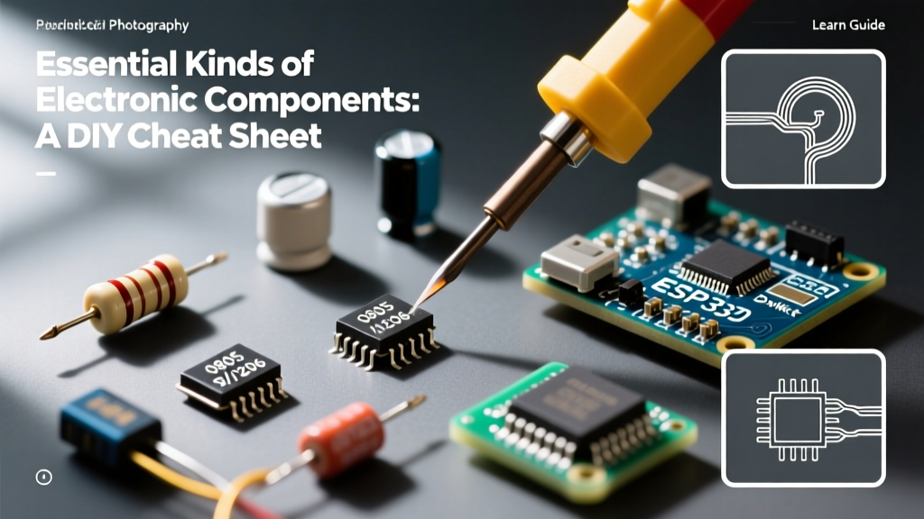
Surface Mount Device (SMD) packaging has shrunk significantly. While hobbyists still rely on 0805 and 0603 imperial sizes, modern consumer electronics and high-density PCBs heavily utilize 0402 and 0201. Note that SMD naming conventions use imperial codes in the US/UK, but metric codes in Asia. This causes frequent procurement errors.
| Imperial Code | Metric Code | Dimensions (mm) | Hand Soldering Feasibility |
|---|---|---|---|
| 1206 | 3216 | 3.2 x 1.6 | Very Easy (Standard iron) |
| 0805 | 2012 | 2.0 x 1.2 | Easy (Fine tip iron) |
| 0603 | 1608 | 1.6 x 0.8 | Moderate (Requires magnification) |
| 0402 | 1005 | 1.0 x 0.5 | Hard (Hot air or reflow oven required) |
| 0201 | 0603 | 0.6 x 0.3 | Extreme (Professional assembly only) |
Industry Rule of Thumb: If you are hand-assembling prototypes in a home lab, standardize your BOM on 0603 (Imperial) components. They are small enough to keep PCB routing clean and dense, but large enough to be easily reworked with a standard Hakko FX-888D soldering station and fine tweezers.
5. 2026 Sourcing & BOM Strategy
Component sourcing has bifurcated into two distinct paths depending on your project phase. For prototyping and hobbyist runs, Asian distributors like LCSC offer staggering economies of scale; a full reel (10,000 pieces) of generic 0402 thick-film resistors costs roughly $1.20 to $1.80. However, for medical, automotive, or aerospace designs where lot traceability and strict tolerance certifications are required, authorized Western distributors like DigiKey and Mouser remain mandatory. Always verify the Moisture Sensitivity Level (MSL) of your ICs before ordering; MSL 3 and above components require baking and vacuum-sealed dry storage to prevent the 'popcorn effect' (internal steam explosion) during reflow soldering.
Frequently Asked Questions
What is the difference between NPN and PNP transistors?
NPN transistors (like the BC547) are turned on by applying a positive voltage to the base relative to the emitter, making them ideal for low-side switching (connecting the load to ground). PNP transistors (like the BC557) require the base to be pulled lower than the emitter to turn on, making them suitable for high-side switching (connecting the load to the positive supply).
Why do my ceramic capacitors squeal or whine?
This is known as piezoelectric acoustic noise. Certain MLCC dielectrics, particularly X7R and X5R, physically deform when subjected to alternating voltages. If the AC ripple frequency falls within the human hearing range (20Hz to 20kHz), the PCB acts as a sounding board, amplifying the vibration into an audible whine. Using thicker PCBs, potting compounds, or switching to C0G dielectrics mitigates this.
For more comprehensive tutorials on basic circuit analysis and component behavior, the All About Circuits DC Electronics textbook remains an exceptional open-source reference for builders of all skill levels.