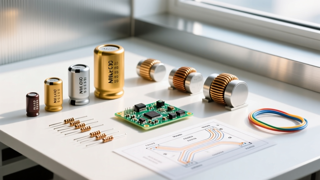

Whether you are routing a simple 555 timer astable multivibrator or designing a 4-layer mixed-signal board in KiCad 8, the schematic is your single source of truth. Understanding the schematic symbols of electronic components is the critical first step in translating abstract circuit theory into physical, functioning hardware. A single misinterpreted symbol can lead to reversed polarity, dead shorts, or destroyed silicon during the prototyping phase.
In this circuit application tutorial, we move beyond basic shape recognition. We will dissect the global standards governing these symbols, explore the nuanced differences in transistor representations, and map 2D schematic symbols to their physical 3D PCB footprints to ensure your next board spin is flawless.
The Foundation: IEEE 315 vs. IEC 60617 Standards
When interpreting the schematic symbols of electronic components, engineers must first recognize which standard their schematic capture software is utilizing. The two dominant global standards are:
- IEEE 315 (US Standard): Predominantly used in North America. It features the classic 'zigzag' line for resistors and specific arc notations for inductors.
- IEC 60617 (International Standard): The standard across Europe and most international datasheets. It replaces the zigzag resistor with a simple rectangular box and uses standardized enclosure outlines for integrated circuits.
Modern EDA tools like Altium Designer 24 and KiCad 8 allow you to toggle between these symbol libraries. According to the SparkFun guide on reading schematics, mixing these standards within a single schematic hierarchy is considered poor design practice and can cause confusion during peer reviews or contract manufacturing hand-offs.
Critical Component Symbols and Real-World Applications
Below is a quick-reference matrix detailing how common components are represented across standards and how they map to physical prototyping realities.
| Component | IEEE 315 Symbol | IEC 60617 Symbol | Common Prototyping Footprint | Application Note |
|---|---|---|---|---|
| Resistor (Fixed) | Zigzag Line | Empty Rectangle | R_0805_2012Metric | Use 1% tolerance (E96 series) for precision feedback loops. |
| Capacitor (Non-Polar) | Two parallel lines | Two parallel lines | C_0603_1608Metric | Place 100nF decoupling caps within 2mm of IC VCC pins. |
| Inductor | Four connected arcs | Series of half-circles | L_1210_3225Metric | Ensure saturation current rating exceeds peak load by 20%. |
| Diode (Schottky) | Triangle with line & 'S' | Triangle with line & 'S' | D_SMA | Use for low forward-voltage drop (Vf) in power rectification. |
Capacitors: Navigating the Polarity Trap
One of the most frequent points of failure in DIY and professional prototyping stems from misreading capacitor polarity symbols. Non-polarized ceramic capacitors (like a standard 100nF X7R) are represented by two parallel lines of equal length. However, polarized capacitors demand strict attention to their symbol variants.
Aluminum Electrolytic vs. Tantalum
For aluminum electrolytic capacitors (e.g., the Panasonic EEUFM series), the symbol typically features one straight line (positive/anode) and one curved line (negative/cathode), often accompanied by a '+' sign.
Tantalum capacitors (e.g., KEMET T491 series) use a different convention. The schematic symbol usually displays two straight parallel lines, but the positive terminal is marked with a '+', while the physical component features a polarity stripe indicating the positive terminal. This is the exact opposite of aluminum electrolytics and aluminum-polymer caps, where the stripe indicates the negative terminal. Reversing a tantalum capacitor during assembly doesn't just fail the circuit; it creates a violent thermal runaway event, often resulting in a small fire.
Transistors: BJT and MOSFET Symbol Nuances
Transistor symbols encode critical information about semiconductor physics and current flow direction. Misreading these is a primary cause of prototype failure.
Bipolar Junction Transistors (BJTs)
The BJT symbol consists of a base, collector, and emitter. The arrow is always on the emitter leg.
- NPN (e.g., 2N3904): The arrow points away from the base. (Mnemonic: 'Not Pointing iN'). Current flows from Collector to Emitter when the Base is pulled high.
- PNP (e.g., 2N3906): The arrow points toward the base. (Mnemonic: 'Pointing iN'). Current flows from Emitter to Collector when the Base is pulled low.
MOSFETs: The High-Side Switching Dilemma
Metal-Oxide-Semiconductor Field-Effect Transistors (MOSFETs) feature a gate, drain, and source, with the substrate/body diode explicitly drawn in the symbol.
For an N-channel enhancement MOSFET (e.g., IRLZ44N), the arrow on the body diode points inward (from source to drain), and the channel line is broken, indicating it is normally off. For a P-channel MOSFET (e.g., IRF9540N), the arrow points outward.
Pro-Tip for Circuit Designers: Never place an N-channel MOSFET on the high-side of a load without a dedicated gate driver or charge pump. If you drive the gate with a 5V microcontroller pin, the source voltage will rise as the load turns on, dropping the Vgs (Gate-to-Source voltage) below the threshold voltage (Vth). The MOSFET will enter the linear region, overheat, and destroy itself. Always use a P-channel MOSFET or a high-side gate driver IC (like the MIC4427) for high-side switching.
Translating 2D Symbols to 3D Footprints
A common misconception among beginners is that the schematic symbols of electronic components dictate physical size. They do not. A schematic symbol for a 10kΩ resistor contains zero physical dimension data. It is the footprint assignment that dictates physical reality.
As detailed in the official KiCad library documentation, mapping the correct footprint to the schematic symbol is a vital step before generating your netlist. Consider the following footprint selection framework for 2026 prototyping:
- 0201 (0.60mm x 0.30mm): Strictly for high-density, machine-assembled production boards. Impossible to hand-solder reliably without a microscope and specialized micro-tweezers.
- 0603 (1.60mm x 0.80mm): The modern sweet spot for commercial production. Hand-solderable by experienced technicians with a fine-tipped iron (e.g., Weller RT4) and flux.
- 0805 (2.00mm x 1.25mm): The gold standard for DIY prototyping, breadboard-to-PCB transitions, and educational kits. Large enough to rework easily with standard solder wick.
- 1206 (3.20mm x 1.60mm): Recommended for power resistors (e.g., 0.5W current shunts) where thermal dissipation and physical clearance are required.
Critical Failure Modes from Schematic Misreads
When reviewing schematics prior to PCB layout, engineers must actively hunt for symbol-to-footprint mismatches. Here are two real-world failure modes that plague prototyping labs:
1. The Op-Amp Pinout Trap
The standard triangle symbol for an Operational Amplifier (like the ubiquitous TL072 or LM358) shows the non-inverting (+) and inverting (-) inputs. However, the physical DIP-8 or SOIC-8 package pinouts vary wildly between manufacturers and specific part families. If your schematic symbol maps Pin 2 to the non-inverting input, but the specific TI datasheet for your chosen LM358 variant maps Pin 3 to the non-inverting input, your negative feedback loop will become a positive feedback loop, turning your precision amplifier into a high-frequency oscillator.
2. Connector Mirror Imaging
When using schematic symbols for multi-pin connectors (like JST-XH or Molex PicoBlade), the 2D symbol often assumes a 'top-down' view of the male header. If the PCB footprint is designed for a 'right-angle' connector, the pin sequence (1-2-3-4) will be physically mirrored on the board. Always verify the 3D STEP model in your EDA software against the physical connector datasheet to ensure Pin 1 aligns correctly.
Frequently Asked Questions (FAQ)
Do schematic symbols show the actual physical orientation of ICs?
No. Schematic symbols for ICs often arrange pins logically (e.g., grouping all power pins on top, signal pins on the sides, and ground pins on the bottom) to make the schematic readable. The physical footprint dictates the actual rotational orientation and pin layout on the PCB.
Where can I find standardized symbol libraries?
For authoritative standard references, All About Circuits outlines the foundational differences between US and EU schematic conventions. Additionally, most modern EDA tools provide verified, community-audited libraries that map IEEE/IEC symbols directly to IPC-compliant footprints.
What does a circle on the gate of a MOSFET symbol mean?
A small circle (bubble) on the gate of a MOSFET symbol indicates a Depletion-mode device (normally ON) rather than an Enhancement-mode device (normally OFF). It acts similarly to a logical NOT gate inversion bubble in digital logic symbols.
Final Thoughts on Schematic Literacy
Mastering the schematic symbols of electronic components requires looking past the basic geometry and understanding the electrical behavior, polarity constraints, and physical footprint implications each symbol represents. By standardizing your library to either IEEE or IEC, rigorously verifying transistor orientations, and meticulously mapping symbols to IPC-verified footprints, you eliminate the most common points of failure in modern circuit prototyping.