
The Unboxing Paralysis: Why Identification Matters
Opening a 500-piece beginner electronics kit—such as the $39.99 Elegoo Super Starter Kit or the $34.50 Rexqualis Ultimate Kit—is a rite of passage for hardware enthusiasts. However, staring at a tangled bag of beige cylinders, black chips, and wire snippets often leads to immediate paralysis. Mastering electronic component identification is the critical first step between a successful breadboard prototype and a short-circuited microcontroller.
In this guide, we bypass generic theory and focus strictly on the physical identification, marking schemes, and failure modes of the exact components you will find in a standard 2026 beginner prototyping kit. Whether you are building an astable multivibrator or interfacing an I2C sensor, knowing exactly what you are holding prevents costly mistakes.
1. Decoding the Resistor Matrix
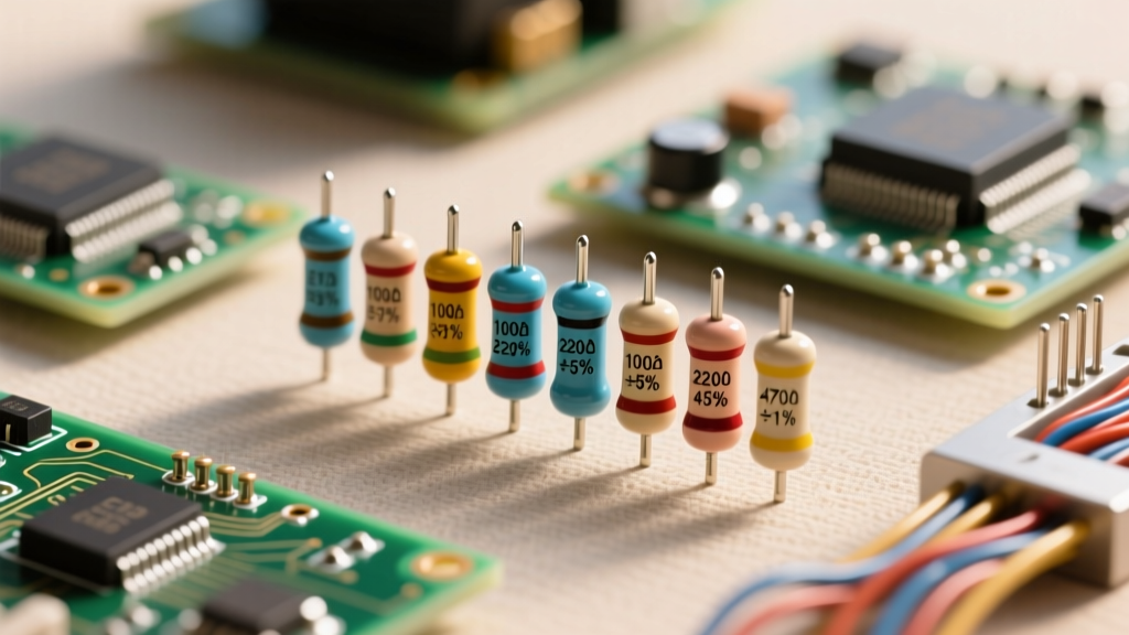
Resistors are the most abundant components in any starter kit. Most kits include 1/4W (0.25W) carbon film resistors with 5% tolerance (gold band). While surface-mount (SMD) resistors dominate commercial manufacturing, through-hole axial resistors remain the standard for breadboarding due to their physical handles.
According to the SparkFun Resistor Tutorial, reading the 4-band color code is a mandatory skill. The first two bands represent significant digits, the third is the multiplier, and the fourth is tolerance.
The Beginner Kit Resistor Cheat Sheet
| Target Value | Color Bands (4-Band) | Primary Prototyping Use Case | Failure Mode Warning |
|---|---|---|---|
| 220Ω | Red-Red-Brown-Gold | Current limiting for standard 5mm red/green LEDs at 5V. | Using 100Ω instead will push >20mA, causing LED thermal runaway. |
| 1kΩ | Brown-Black-Red-Gold | Base current limiting for NPN transistors (e.g., 2N2222). | Too high (e.g., 100kΩ) prevents the transistor from reaching saturation. |
| 4.7kΩ | Yellow-Violet-Red-Gold | I2C pull-up resistors for SDA/SCL lines (e.g., MPU6050). | Omitting these leaves the bus floating, causing random data corruption. |
| 10kΩ | Brown-Black-Orange-Gold | Pull-down resistors for tactile switches; voltage dividers. | Using 10Ω creates a near-short to ground, draining power supplies. |
| 100kΩ | Brown-Black-Yellow-Gold | High-impedance pull-ups; timing circuits with small capacitors. | Susceptible to electromagnetic interference (EMI) noise on breadboards. |
Pro-Tip: Always verify resistor values with a digital multimeter (DMM) before inserting them into a live circuit. Manufacturing errors in budget kits occasionally result in mis-banded components.
2. Capacitor Conundrums: Ceramic vs. Electrolytic
Capacitors store and release electrical energy, acting as local energy reservoirs or signal filters. Beginner kits typically contain two distinct physical types, and confusing them is a primary cause of catastrophic circuit failure.
Ceramic Disc Capacitors (Non-Polarized)
These look like small, flat, brownish-orange discs with two wire leads. Because they are non-polarized, they can be inserted in either direction. They are marked with a three-digit code representing picofarads (pF). The first two digits are significant, and the third is the multiplier (number of zeros).
- Code '104': 10 + 0000 pF = 100,000 pF = 100 nF = 0.1 µF. This is the most common decoupling capacitor in your kit, used across the VCC and GND pins of ICs to filter high-frequency noise.
- Code '22p' or '220': Used in high-frequency oscillator circuits, such as the 16MHz crystal oscillator required for standalone ATmega328P microcontrollers.
Electrolytic Capacitors (Polarized)
These are cylindrical, usually encased in a black or blue aluminum sleeve. They have strict polarity. The sleeve features a prominent stripe with minus signs (-) indicating the negative (cathode) lead. Additionally, the positive lead is often manufactured slightly longer than the negative lead.
⚠️ Critical Failure Mode: Reverse-biasing an electrolytic capacitor causes the internal dielectric oxide layer to break down. This leads to rapid internal heating, gas generation, and ultimately a violent venting or explosion. Always double-check the negative stripe against the ground rail before applying power. For a deeper dive into dielectric physics, refer to the SparkFun Capacitor Guide.
3. Semiconductor Pinouts: Transistors and Diodes
Semiconductors control the flow of electricity and are foundational to logic and amplification. Identifying their orientation is non-negotiable.
The 1N4007 Rectifier Diode
Diodes allow current to flow in only one direction. The 1N4007 is the standard general-purpose diode in almost every kit. It features a black cylindrical body with a single grey or white band at one end. This band marks the cathode (negative side). Current flows from the un-banded anode to the banded cathode. If you are using it for flyback protection across a relay coil, the band must face the positive voltage rail.
Bipolar Junction Transistors (BJTs): 2N2222 and BC547
Most kits include NPN transistors in the TO-92 package, which looks like a small black plastic half-cylinder with three leads. The most common models are the 2N2222 (higher current, up to 800mA) and the BC547 (lower current, up to 100mA).
Pinout Identification (TO-92 Package):
- Hold the transistor so the flat side with the text is facing you and the leads are pointing downward.
- For the 2N2222, the pins from left to right are: Emitter (E), Base (B), Collector (C).
- For the BC547, the pins from left to right are: Collector (C), Base (B), Emitter (E).
Note: Never assume pinouts based on package shape alone. Always verify the specific manufacturer's datasheet, as some regional variants of the 2N2222 (like the P2N2222A) reverse the E and C pins.
Verifying Semiconductors with a DMM
Set your multimeter to the Diode Test Mode (usually indicated by a triangle and a line symbol). Place the red probe on the Base and the black probe on the Emitter. An NPN transistor will show a forward voltage drop of approximately 0.6V to 0.7V. Reversing the probes should yield an 'OL' (Open Loop) reading. This quick test confirms the component is alive and verifies the pinout.
4. Integrated Circuits (ICs) and the Pin 1 Rule
Integrated circuits pack complex logic into a single package. The most ubiquitous IC in beginner kits is the NE555 Timer, used for generating precise time delays or oscillations. According to the official Texas Instruments LM555 Datasheet, proper pin identification is critical for internal comparator referencing.
How to find Pin 1 on any DIP (Dual In-line Package) IC:
- The Notch: Look at the top of the black plastic body. One end will have a semi-circular cutout or notch. Position the IC so the notch is at the top (or left). Pin 1 is always the top-left pin.
- The Dot: Many ICs also feature a small indented dot molded into the plastic directly next to Pin 1.
- The Bevel: Some modern DIP packages have a slightly beveled edge running along the side starting from Pin 1.
Once Pin 1 is identified, pins are counted sequentially down the left side, across the bottom notch, and up the right side. For the NE555, Pin 1 is Ground, Pin 8 is VCC, and Pin 3 is the Output. Wiring VCC to Ground and Ground to VCC will instantly destroy the internal silicon die via thermal overstress.
Essential 2026 Tools for Component Identification
Visual identification is prone to human error, especially with aging eyes or poorly printed markings. Equip your workbench with these specific, cost-effective tools to guarantee accuracy:
- Uni-T UT89X Digital Multimeter (~$29.99): A robust, entry-level DMM featuring a dedicated LED test mode (which outputs up to 9V to properly illuminate high-forward-voltage LEDs) and precise capacitance measurement down to 10nF.
- LCR-T4 Transistor Tester (~$14.99): Often included in premium kits or bought separately, this ZIF-socket device automatically identifies BJTs, MOSFETs, JFETs, and diodes, displaying the exact pinout and hFE (gain) on an LCD screen. It is the single greatest time-saver for sorting mixed bags of transistors.
- 10x Jeweler's Loupe or Digital Microscope: Essential for reading the microscopic 3-digit codes on ceramic capacitors or verifying the orientation of SMD components if your kit includes a surface-mount soldering practice board.
Summary: Build a Component Library
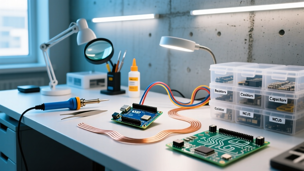
Do not rely on memory when prototyping. The most efficient workflow for electronic component identification is to immediately sort your kit into compartmentalized storage bins labeled with both the value and the physical marking code. By combining visual inspection, standardized marking rules, and DMM verification, you eliminate the guesswork and lay a professional foundation for every circuit you design.