
The Anatomy of a Perfect WLED Flasher Setup
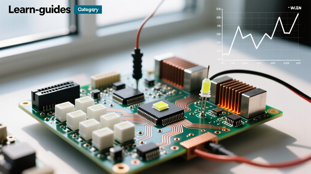
When builders and DIY electronics enthusiasts talk about a wled flasher, they are rarely referring to just the software utility used to write firmware. In the modern addressable LED community, the term encompasses the entire hardware ecosystem: the ESP32 microcontroller, the logic level shifters, the screw terminals, and the power injection boards that receive the flashed WLED firmware and drive the WS2812B, SK6812, or APA102 LED strips. Choosing the right WLED flasher kit is the difference between a plug-and-play smart lighting setup and a flickering, voltage-starved mess that requires constant troubleshooting.
In this comprehensive kit and equipment roundup, we evaluate the best barebones development boards, dedicated WLED controller shields, and audio-reactive kits available. Whether you are building a simple 5-meter bias lighting rig behind your monitor or a 2,000-LED synchronized holiday roofline display, selecting the correct hardware foundation is critical. We will also cover the specific software flashing tools required to get your hardware online, common wiring failure modes, and the exact logic-level shifting chips you need to prevent data corruption.
Top ESP32 Dev Boards for WLED Flashing (The Brains)
The core of any WLED flasher setup is the microcontroller. While the older ESP8266 (like the Wemos D1 Mini) was the original standard, it is severely limited by its single-core processor, lack of Bluetooth, and restricted RAM, capping out at around 1,000 LEDs. For any serious 2026 project, the ESP32 is the mandatory choice. However, not all ESP32 dev boards are created equal when it comes to flashing and driving LEDs.
Generic ESP32 DevKit V1 (30-Pin vs. 38-Pin)
The generic ESP32 DevKit V1 is the most common entry-level wled flasher board, usually priced between $5 and $8. However, buyers must be highly cautious about the USB-to-UART bridge chip used on the board. Boards equipped with the CP2102 chip are generally plug-and-play across Windows, Mac, and Linux. Conversely, boards using the CH340G or CH9102 chips frequently require manual driver installations and are notorious for failing during the initial firmware flashing process, throwing 'Failed to connect to ESP32: Timed out waiting for packet header' errors in the flashing utility.
Furthermore, the 38-pin DevKit V1 boards often have a physical design flaw: the dual rows of header pins are spaced too closely to fit standard breadboards without bending the pins. The 30-pin variants are generally preferred for custom soldering and wiring to LED strips. When wiring a generic DevKit V1 for WLED, the standard data output pin is GPIO 16 (RX2), though this can be remapped in the WLED LED preferences menu post-flash.
Dedicated WLED Controller Shields & Pre-Flashed Kits
For builders who want to skip the breadboard phase and move straight to a permanent, soldered installation, dedicated WLED controller shields are the ultimate upgrade. These kits integrate the ESP32, the logic level shifter, and high-current screw terminals onto a single, purpose-built PCB.
The QuinLED Dig-Uno remains the gold standard in the community. Unlike generic dev boards that output a weak 3.3V logic signal, the Dig-Uno features a built-in SN74AHCT125 level shifter. This chip translates the ESP32's 3.3V data signal to a robust 5V signal, which is the actual voltage requirement for the WS2812B data line. Skipping this level shifter on runs longer than 2 meters is the number one cause of random LED flickering and color shifting. The Dig-Uno also includes a dedicated 5V power input terminal that bypasses the ESP32's fragile AMS1117 voltage regulator, allowing you to safely inject up to 15 Amps of current directly to the LED strip without melting the dev board's traces.
For larger installations, the QuinLED Dig-Quad allows you to flash WLED firmware and control four separate LED strips simultaneously using the ESP32's I2S and RMT hardware channels, supporting up to 4,800 LEDs at 30 FPS.
Audio-Reactive WLED Flasher Kits (I2S Microphones)
A massive trend in the WLED community is audio-reactive lighting. Standard analog microphones (like the MAX9814) suffer from terrible latency and background noise hum. The modern standard for an audio-reactive wled flasher kit involves an ESP32 paired with an INMP441 I2S digital MEMS microphone.
When sourcing an audio-reactive kit, ensure the ESP32 board breaks out the necessary I2S pins (WS, BCK, SD, L/R). The WLED 'AudioReactive' usermod requires specific GPIO assignments to function correctly without conflicting with the LED data pins. Pre-configured audio-reactive WLED shields are now available from boutique electronics makers on Tindie and Etsy, which wire the INMP441 directly to the ESP32's GPIO 32 (WS), GPIO 33 (BCK), and GPIO 25 (SD), providing a seamless flashing and setup experience.
Hardware Comparison & Pricing Matrix
| WLED Flasher Kit / Board | Est. Price | Level Shifter | Terminals | Max LED Capacity | Best Use Case |
|---|---|---|---|---|---|
| Generic ESP32 DevKit V1 (CP2102) | $6.00 | None (3.3V) | None (Solder) | ~1,500 (Single Run) | Prototyping, short strips |
| Wemos D1 Mini ESP32 | $8.00 | None (3.3V) | None (Solder) | ~1,000 | Tight spaces, wearable |
| QuinLED Dig-Uno (ESP32) | $26.00 | SN74AHCT125 (5V) | Screw (15A) | ~1,500 (Reliable) | Permanent architectural installs |
| QuinLED Dig-Quad (ESP32) | $42.00 | SN74AHCT125 (5V) | Screw (Multi) | ~4,800 (4 Runs) | Mega-trees, rooflines |
| ESP32 + INMP441 Audio Shield | $18.00 | Varies | Screw (10A) | ~1,000 | Music sync, gaming rooms |
Software Flashing: WebSerial vs. USB Utility
Once you have your hardware kit, you must flash the WLED firmware. The community has largely moved away from the clunky Arduino IDE compilation process in favor of pre-compiled binaries. The primary tool is the WLED Web Flasher, which utilizes the WebSerial API. This allows you to plug your ESP32 directly into your PC, open Chrome or Edge, and flash the firmware straight from the browser.
Critical Flashing Tip: The WebSerial API is strictly incompatible with Safari and Firefox. If your browser cannot detect the COM port, switch to Chromium-based browsers. Furthermore, if you are using an ESP32-C3 or ESP32-S3 mini board, these chips lack an automatic boot-mode circuit. You must physically wire GPIO 9 to GND (or hold the 'BOOT' button on the dev board) while plugging in the USB cable to force the chip into download mode before the web flasher can handshake with the silicon.
If the web flasher fails due to USB timeout errors, the fallback is the ESP Flash Download Tool (Windows) or esptool.py (Mac/Linux). When using esptool.py via the command line, the standard write command for an ESP32 is: esptool.py --chip esp32 --port COM3 write_flash -z 0x10000 WLED_0.14.0_ESP32.bin. Always ensure you flash the correct binary for your specific ESP32 variant (e.g., standard ESP32 vs. ESP32-S2 vs. ESP32-C3), as flashing the wrong architecture will result in a boot-loop.
Power Injection & Wiring Failure Modes to Avoid
The most catastrophic failure mode in a wled flasher setup is not a software bug; it is a hardware power fault. Addressable LEDs draw massive amounts of current. A standard 60-LED/meter WS2812B strip draws approximately 3.6 Amps per meter at full white brightness. A 5-meter strip will pull 18 Amps.
Failure Mode 1: The AMS1117 Meltdown. Beginners often attempt to power the ESP32 and a short LED strip directly from the dev board's 5V and GND pins via USB. The USB port supplies a maximum of 0.5A to 2A. More importantly, the onboard AMS1117 voltage regulator on cheap clone boards is rated for roughly 800mA. If you back-feed 5V from the LED strip into the 5V pin of the ESP32, and the USB is also connected, you can create a ground loop or overheat the regulator, literally melting the plastic casing of the chip and destroying the board. Always use a dedicated 5V power supply (like a Mean Well LRS-300-5) wired directly to the LED strip's power rails, with only the Data and GND lines connected to the ESP32.
Failure Mode 2: Voltage Drop and Data Corruption. If you push 18 Amps through the thin copper traces of a flexible LED strip, the voltage at the 3-meter mark will drop below 4.5V. This causes the LEDs at the end of the strip to turn brown/yellow instead of white, and eventually causes the data signal to degrade, resulting in random strobing. You must implement power injection—running 18 AWG or 16 AWG silicone wire parallel to the LED strip and soldering it to the 5V and GND pads every 2.5 meters.
Safety Warning: Always install an inline automotive blade fuse (rated slightly higher than your expected draw, e.g., 20A for a 15A strip) on the positive 5V wire immediately after the power supply terminals. In the event of a short circuit or a water ingress event on outdoor holiday lights, this fuse will blow before your wires catch fire. For more on electrical safety, refer to the WLED Getting Started Guide.
By selecting the right ESP32 board, integrating a proper SN74AHCT125 level shifter, and respecting the high-current demands of addressable LEDs, your wled flasher kit will provide years of stable, high-framerate smart lighting control.