
The Hidden Vulnerabilities of TFT Display Modules
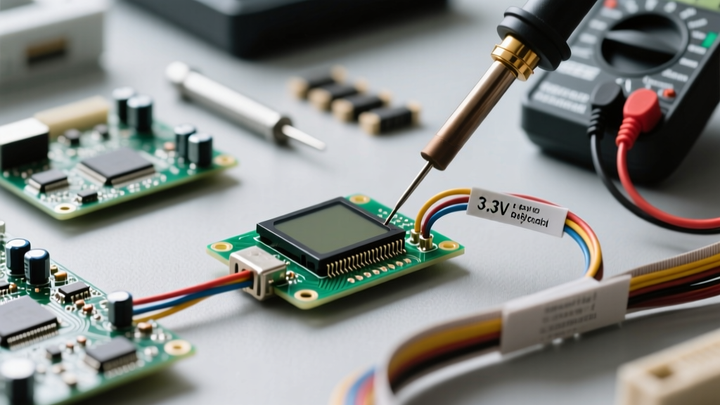
Integrating a tft display module into a custom microcontroller project is a rite of passage for electronics enthusiasts. Whether you are building a custom telemetry dashboard for a racing drone, a smart home thermostat, or an industrial monitoring rig, Thin-Film-Transistor (TFT) LCDs offer vibrant colors and high refresh rates. However, beneath the protective polarizing film lies a highly sensitive ecosystem of fragile silicon controllers, microscopic Flexible Printed Circuit (FPC) traces, and current-hungry backlight arrays.
While most DIYers focus purely on software libraries like TFT_eSPI or Adafruit_GFX, hardware-level safety and wiring best practices are frequently ignored. A single wiring oversight can result in catastrophic failure modes, ranging from melted FPC traces to permanently degraded SPI gate oxides. This guide outlines the critical electrical safety protocols, voltage translation frameworks, and thermal management strategies required to ensure your tft display module operates reliably for years without degradation.
Voltage Mismatches: The Silent Killer of TFT Panels
The most common cause of premature tft display module failure is logic voltage mismatch. The vast majority of modern TFT controller ICs—such as the ILI9341, ST7789V, and GC9A01—are strictly 3.3V devices. Their VDD I/O pins are not 5V tolerant. Connecting these pins directly to the 5V digital outputs of a classic Arduino Uno or Mega does not always cause immediate, explosive failure. Instead, it initiates a slow, silent degradation of the silicon gate oxide layer inside the controller IC.
Over weeks or months of operation, this overvoltage stress leads to 'ghosting' on the screen, stuck pixels, SPI bus lockups, and eventually, a completely unresponsive display. To prevent this, you must implement proper logic level translation when bridging 5V microcontrollers to 3.3V TFT modules.
Implementing Safe Logic Level Translation
When shifting SPI signals (MOSI, SCK, CS, DC) from 5V to 3.3V, unidirectional level shifters are preferred due to their lower capacitance and higher switching speeds. The CD4050BE hex non-inverting buffer is an excellent, low-cost choice for SPI lines. For bidirectional lines (like the MISO pin or I2C touch controllers), a MOSFET-based bidirectional shifter utilizing BSS138 transistors is required. Avoid using resistor voltage dividers for high-speed SPI buses; the parasitic capacitance of the resistor network and the TFT input pin will form a low-pass filter, rounding off the square wave edges and causing data corruption at clock speeds above 10 MHz.
| TFT Controller | VCC Logic | VDD I/O Tolerance | Max Safe SPI Clock | Backlight Vf (Typical) |
|---|---|---|---|---|
| ILI9341 | 2.8V - 3.3V | 3.6V (Absolute Max) | 15.1 MHz | 3.2V |
| ST7789V | 2.8V - 3.3V | 3.6V (Absolute Max) | 62.5 MHz | 3.4V |
| GC9A01 (Round) | 3.3V | 3.6V (Absolute Max) | 60 MHz | 3.2V |
| SSD1351 (OLED) | 3.3V | 3.6V (Absolute Max) | 20 MHz | N/A (Self-Emissive) |
Source data synthesized from manufacturer datasheets and the SparkFun Logic Levels Guide.
Backlight Power Delivery and Thermal Safety
The backlight array of a tft display module is essentially a bank of high-intensity white LEDs wired in series or parallel. A standard 2.4-inch to 3.2-inch TFT panel requires anywhere from 50mA to 150mA to illuminate the backlight fully. This presents two major safety hazards for DIY wiring.
The 'Direct 5V' Backlight Mistake
Many budget tft display modules omit the current-limiting resistor on the backlight (LED) pin to save manufacturing costs. If you wire this pin directly to a 5V source, Ohm's law dictates that the LEDs will attempt to draw massive current, limited only by their internal resistance and the power supply's capacity. This will instantly exceed the forward voltage rating (typically 3.2V to 3.4V), causing the LEDs to overheat, shift color temperature, and burn out within minutes. Worse, the thin copper traces on the FPC ribbon can act as a fuse, melting and permanently severing the backlight circuit.
Best Practice: Never drive the backlight directly from a microcontroller GPIO pin. Most MCU pins are rated for an absolute maximum of 20mA to 40mA. Instead, use a PNP transistor (like the BC327) or an N-channel MOSFET (like the 2N7000) to switch the backlight current from a dedicated 5V or 3.3V power rail. Always place a current-limiting resistor in series. For a 5V rail and a 3.2V backlight drawing 50mA, a 36-ohm (use standard 39-ohm) 1/4W resistor is mathematically required to ensure safe thermal dissipation.
Mechanical Safety: Preserving the FPC and Glass
The physical construction of a tft display module is inherently fragile. The glass substrate is bonded to a Flexible Printed Circuit (FPC) using anisotropic conductive film (ACF). This bond is highly sensitive to mechanical shear and bending fatigue.
- The 3mm Bend Radius Rule: Never fold the FPC ribbon cable at a sharp 90-degree angle. Maintain a minimum bend radius of 3mm. Sharp creases will fracture the microscopic copper vias inside the polyimide layers, resulting in missing color channels or dead touch zones.
- ESD Protocols: The exposed connector pins on the FPC are direct pathways to the CMOS controller IC. Electrostatic Discharge (ESD) from a human finger can easily exceed 2000V, instantly punching through the gate oxides of the SPI input buffers. Always ground yourself via an ESD wrist strap or touch a grounded chassis before handling bare TFT modules. For deeper insights on component protection, refer to the ESD Association Fundamentals.
- Z-Axis Pressure: When mounting the display into an enclosure, ensure that no screws or standoffs apply pressure directly to the glass perimeter. The glass is under high internal tension; localized pressure points will cause spontaneous shattering, especially during temperature fluctuations.
SPI Signal Integrity and Grounding Topologies
TFT displays rely on high-speed SPI (Serial Peripheral Interface) buses to push pixel data. When operating at clock speeds of 40 MHz to 80 MHz, the wiring topology becomes a critical safety and reliability factor. Long, unshielded jumper wires act as antennas, radiating EMI and picking up cross-talk.
Expert Wiring Framework: When using ribbon cables or jumper wires between your MCU and the tft display module, adopt a 'GND-Signal-GND' topology. Place a ground wire between every single high-speed SPI line (e.g., GND, MOSI, GND, SCK, GND, CS). This provides an immediate, low-impedance return path for high-frequency signals, drastically reducing inductive ringing and preventing the SPI bus from misinterpreting noise as clock pulses, which can cause screen tearing or controller lockups.
Furthermore, ensure that the 3.3V power rail feeding the TFT module is decoupled properly. Place a 100nF ceramic capacitor and a 10uF tantalum capacitor as close to the VCC and GND pins of the TFT module as physically possible. This local energy reservoir prevents voltage sag during high-contrast screen refreshes, which can otherwise trigger brown-out resets in the display controller.
Diagnostic Framework: Identifying Hardware Damage
If your tft display module fails to initialize, use this diagnostic framework to determine if the issue is software-related or if permanent hardware damage has occurred due to unsafe wiring practices.
- Pure White Screen: Usually indicates a floating RESET pin or a missing 3.3V logic supply to the controller. Check your wiring; the silicon is likely still safe.
- Garbled Colors / Inverted Axes: Often a software initialization sequence mismatch (e.g., sending ILI9341 commands to an ST7789 panel). However, if the colors randomly shift during operation, it indicates SPI signal degradation or 5V logic damage to the MISO/MOSI pins.
- Flickering Backlight: Insufficient current delivery from the power supply, or a missing current-limiting resistor causing the LEDs to thermally cycle and trigger internal protection diodes.
- Completely Black Screen (No Backlight, No Data): Verify the FPC traces. If you previously wired the backlight directly to 5V without a resistor, the internal FPC trace has likely vaporized. This is permanent, unrepairable hardware damage.
Conclusion
Treating a tft display module with the respect demanded by its sensitive internal architecture is the difference between a prototype that works on the bench and a product that survives in the field. By rigorously managing logic voltages, implementing proper backlight current limiting, respecting the mechanical limits of the FPC, and engineering your SPI grounding topology, you ensure vibrant, reliable visual output for your electronics projects. For further reading on safe microcontroller integrations, the Adafruit 2.8" TFT Touch Shield Guide offers excellent schematic references for commercial-grade level shifting and decoupling implementations.