
The Shift to Surface Mount Technology (SMT)
In modern electronics manufacturing and advanced DIY prototyping, through-hole technology (THT) has largely been relegated to heavy-duty power components and legacy designs. Today, SMT electronic components dominate the landscape. Surface Mount Technology allows for higher component density, reduced parasitic inductance, and automated assembly via pick-and-place machines. As of 2026, the miniaturization trend continues to push boundaries, with 01005 (imperial) and even 008004 packages becoming increasingly common in consumer wearables and IoT devices.
However, transitioning from through-hole to surface mount design (SMD) introduces a steep learning curve regarding package nomenclature, soldering thermodynamics, and specialized tooling. This guide breaks down the fundamentals of SMT components, providing actionable frameworks for selecting, handling, and soldering them.
Decoding SMT Electronic Component Packages: The Metric vs. Imperial Trap
The most common point of failure for beginners ordering SMT electronic components is the naming convention for passive parts (resistors, capacitors, and inductors). The industry uses a four-digit code representing length and width. The critical catch? North American suppliers often use Imperial codes (inches), while Asian manufacturers and datasheets frequently use Metric codes (millimeters).
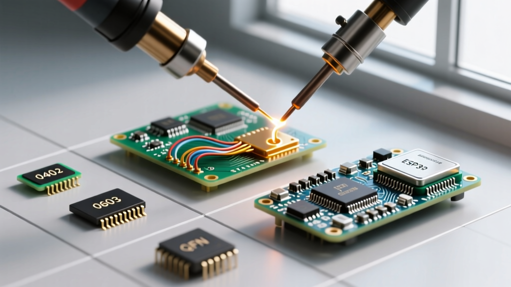
For example, an '0603' capacitor in the US is 0.06 x 0.03 inches. In a Japanese datasheet, '0603' means 0.6 x 0.3 millimeters (which is the Imperial '0201' size). Ordering the wrong standard results in components that are either impossibly small to hand-solder or too large for your PCB footprints.
Standard Passive Package Comparison Matrix
| Imperial Code | Metric Code | Dimensions (L x W mm) | Power Rating (Typical Resistor) | DIY Prototyping Viability |
|---|---|---|---|---|
| 1206 | 3216 | 3.2 x 1.6 | 1/4 W (250 mW) | Excellent (Easy hand soldering) |
| 0805 | 2012 | 2.0 x 1.25 | 1/8 W (125 mW) | Very Good (Standard DIY choice) |
| 0603 | 1608 | 1.6 x 0.8 | 1/10 W (100 mW) | Good (Requires magnification) |
| 0402 | 1005 | 1.0 x 0.5 | 1/16 W (63 mW) | Difficult (Needs hot air & microscope) |
| 0201 | 0603 | 0.6 x 0.3 | 1/20 W (50 mW) | Extreme (Factory reflow only for most) |
Active Component Packages: Beyond the Basics
While passives use simple rectangular codes, integrated circuits (ICs) utilize a variety of complex SMT packages. Understanding these is vital for PCB layout and thermal management.
- SOIC (Small Outline Integrated Circuit): The SMT equivalent of the classic DIP chip. Features gull-wing leads with a 1.27mm pitch. Highly forgiving for hand soldering.
- QFP (Quad Flat Package): Features leads on all four sides. Pitch sizes range from 1.0mm down to 0.4mm. Fine-pitch QFPs (0.5mm and below) require drag-soldering techniques and high-quality flux.
- QFN (Quad Flat No-leads): Features pads instead of protruding leads, plus a large exposed thermal pad on the bottom. QFNs are excellent for high-frequency RF designs due to low lead inductance, but they mandate the use of a hot air rework station or reflow oven to solder the hidden ground pad.
- BGA (Ball Grid Array): Uses an array of solder balls on the underside of the chip. BGA is mandatory for high-pin-count processors (like FPGAs or modern ARM Cortex-M7 MCUs). Hand soldering is virtually impossible; it requires precise stencil application, Type 5 or Type 6 solder paste, and controlled reflow profiling.
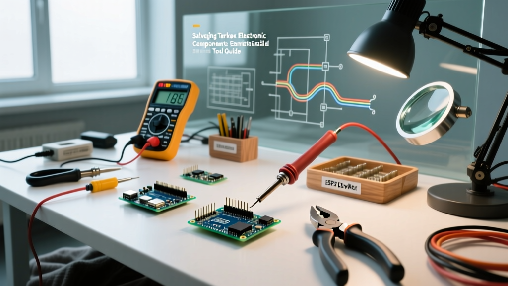
Essential Tooling for SMT Assembly
Working with SMT electronic components demands precision tools. Attempting to solder 0603 or 0402 parts with a standard $20 soldering iron and naked eye will lead to immense frustration and damaged pads.
Pro-Tip: Never skimp on flux when working with SMT. A high-quality no-clean tacky flux (like Amtech NC-559-V2-TF or MG Chemicals 8341) is arguably more important than the soldering iron itself. Flux breaks down surface oxidation and relies on surface tension to pull molten solder perfectly into the pad and component termination.
Recommended 2026 Bench Setup
- Magnification: An AmScope SE400-Z binocular or trinocular stereo microscope (approx. $350-$400) with a 0.5x Barlow lens for working distance. Digital USB microscopes often suffer from latency and poor depth perception.
- Soldering Station: A fast-recovery station like the Hakko FX-951 ($230) or JBC CD-2BQE ($450+). SMT pads act as heat sinks; irons that cannot recover thermal mass instantly will cause cold joints.
- Hot Air Rework Station: The Quick 861DW ($145-$160) remains the gold standard for DIY and prosumer labs. It provides stable airflow and precise temperature control necessary for QFN and BGA rework.
- Tweezers: Titanium, non-magnetic, anti-acid tweezers with ultra-fine tips (e.g., Vetus ST-11 or Dumont #5). Titanium prevents solder from sticking to the tweezers if you accidentally touch the iron.
Step-by-Step: Hand Soldering an 0805 SMT Resistor
Hand soldering is entirely viable for 1206, 0805, and 0603 components if you follow a strict thermodynamic process. According to SparkFun's SMT guidelines, the 'tack and flow' method yields the most reliable joints.
- Prep the Pad: Apply a tiny amount of liquid or tacky flux to one of the PCB pads.
- Tin the Iron: Clean your iron tip on a brass sponge, then apply a microscopic bead of 63/37 leaded solder (or SAC305 lead-free if required by your project specs).
- Tack One Side: Hold the 0805 resistor flat against the PCB with your tweezers. Touch the tinned iron to the prepped pad. The solder will melt and flow onto the component's end cap. Remove the iron, hold the component still for 2 seconds until the solder solidifies.
- Solder the Second Side: Apply a touch of flux to the second pad. Touch the iron with a tiny bit of fresh solder to the second pad and component cap simultaneously. The surface tension will pull the solder into a smooth fillet.
- Inspect: A good SMT joint should look like a smooth, concave 'ski slope' between the pad and the component. Convex blobs indicate too much solder or insufficient flux.
Reflow Soldering and Solder Paste Dynamics
For boards with dozens of SMT electronic components, hand soldering is inefficient. Reflow soldering uses solder paste—a sticky mixture of microscopic solder spheres and chemical flux.
When ordering solder paste, you must match the 'Type' to your component pitch. As outlined by IPC standards (specifically IPC J-STD-005), Type 3 paste (25-45µm sphere size) is fine for 0805 and 0.5mm pitch ICs. However, if you are placing 0402 passives or 0.4mm pitch QFPs, you must upgrade to Type 4 (20-38µm) or Type 5 (15-25µm) to prevent solder bridging and micro-balling.
For lead-free SAC305 paste, your reflow profile must hit a peak temperature of roughly 240°C to 245°C, staying above the 217°C liquidus line for about 45-60 seconds to ensure proper intermetallic compound (IMC) formation without damaging sensitive silicon or melting plastic connectors.
Common SMT Failure Modes and Troubleshooting
Even experienced engineers encounter SMT defects. Recognizing these failure modes is critical for yield improvement:
- Tombstoning: A passive component stands up on one end like a gravestone. Cause: Uneven heating during reflow. One pad reaches solder liquidus before the other, and the surface tension of the molten solder pulls the component upright. Fix: Ensure thermal relief on pads is symmetrical; avoid routing heavy ground planes directly to only one pad of a small capacitor without thermal vias.
- Solder Bridging: Two adjacent IC pins are shorted by a blob of solder. Cause: Excessive solder paste volume, incorrect stencil thickness (use 4 mil or 5 mil stencils for fine pitch), or oxidized paste. Fix: Apply generous liquid flux and use a clean, fluxed solder wick to draw the excess solder away via capillary action.
- Head-in-Pillow (HiP): Common in BGA components. The solder ball on the component melts, and the paste on the PCB melts, but they fail to coalesce into a single joint, resting against each other like a head on a pillow. Cause: Warped PCB or component during the reflow cycle, or oxidized component balls. Fix: Use a reflow oven with a controlled soak zone to equalize thermal mass before the final ramp-to-peak.
Summary
Mastering SMT electronic components requires a shift in mindset from mechanical connections to thermodynamic and chemical processes. By respecting the Imperial/Metric naming conventions, investing in proper optical and thermal tooling, and understanding the chemistry of solder paste, you can reliably prototype and manufacture high-density, high-frequency PCBs right from your home lab.