
Decoding the Core Question: What Is the Potentiometer in Modern Circuits?
When hobbyists and engineering students first ask, "what is the potentiometer," they are usually met with a simplistic answer: a variable resistor used for volume knobs and dimmer switches. While functionally true at a macro level, this definition fails entirely in the context of professional PCB design and precision prototyping. To truly understand what is the potentiometer from an engineering perspective, we must view it as a three-terminal electromechanical transducer that translates mechanical displacement into a precise voltage division ratio.
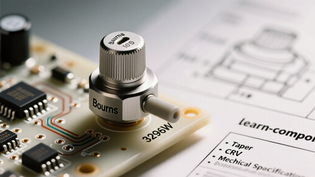
In this datasheet breakdown, we are moving past basic theory. We will dissect the industry-standard Bourns 3296W Multiturn Trimming Potentiometer (specifically the 3296W-1-103LF 10kΩ model). By reading the manufacturer's spec sheet line-by-line, we will uncover the hidden metrics—like Contact Resistance Variation (CRV) and actuation torque—that separate a reliable precision circuit from a noisy, failure-prone prototype.
Datasheet Autopsy: Decoding the Bourns 3296W Part Number
Before analyzing the electrical tables, we must decode the component's nomenclature. The Bourns 3296 series is a cermet (ceramic-metal) multiturn trimpot, heavily favored in calibration circuits, op-amp feedback loops, and sensor offset nulling. Let us break down the specific part number 3296W-1-103LF:
- 3296: The base series designator, indicating a 3/8-inch square, multiturn cermet trimmer.
- W: The pinout configuration. 'W' denotes top-adjust with a specific lead spacing optimized for through-hole breadboarding and PCB mounting.
- 1: The packaging code (tube packaging for manual insertion).
- 103: The resistance code. '10' followed by '3' zeros equals 10,000 ohms (10kΩ).
- LF: Lead-free, indicating RoHS compliance, which dictates the specific soldering temperature profiles you must use during wave or reflow soldering.
Understanding this nomenclature is the first step in answering what is the potentiometer when sourcing components from distributors like DigiKey or Mouser. You are not just buying "a 10k pot"; you are buying a specific mechanical footprint with a defined thermal profile.
Electrical Specifications & The Critical CRV Metric
Open the Bourns 3296 Datasheet and navigate to the Electrical Characteristics table. Most beginners stop at the Resistance Tolerance (±10%). However, for precision analog design, the most critical metric on this page is the Contact Resistance Variation (CRV).
Why CRV Matters More Than Total Tolerance
The datasheet specifies a CRV of ≤ 3% or 3 ohms (whichever is greater). CRV measures the maximum variation in contact resistance between the wiper and the resistive track as the shaft is rotated. If you are using the 3296W as a simple rheostat to limit current to an LED, CRV is irrelevant. But if you are using it in the feedback network of a low-noise operational amplifier to set a precise gain, a sudden 3-ohm jump caused by wiper micro-stutters will introduce voltage noise and DC offset errors into your signal chain.
| Parameter | Spec Sheet Value | Real-World Prototyping Impact |
|---|---|---|
| Resistance Tolerance | ±10% | End-to-end resistance can vary from 9kΩ to 11kΩ. Requires software calibration in microcontroller ADC reads. |
| Contact Resistance Variation (CRV) | ≤ 3% or 3Ω | Determines the noise floor when adjusting gain in sensitive audio or sensor pre-amps. |
| Power Rating (70°C) | 0.5 Watts | Maximum current through the 10kΩ track is ~7mA. Exceeding this causes thermal runaway and track burnout. |
| Temp Coefficient (TCR) | ±100 ppm/°C | For every 10°C rise in PCB temp, resistance shifts by 0.1%. Critical for outdoor or high-heat enclosures. |
Mechanical Limits & Actuation Torque Physics
Answering "what is the potentiometer" also requires understanding its mechanical reality. The 3296W is a multiturn device. The datasheet specifies 25 electrical turns to traverse the full resistive track. This translates to a resolution of roughly 0.04% per degree of rotation, allowing for micro-adjustments that a single-turn pot simply cannot achieve.
Actuation Torque and Wiper Degradation
The spec sheet lists the actuation torque at a maximum of 200 gf·cm (gram-force centimeters). This is the physical resistance you feel when turning the brass adjustment screw. During prototyping, if you use a metal jeweler's screwdriver and apply excessive downward axial force while turning, you risk exceeding the mechanical stop limits. The datasheet notes an end stop torque of 20 kgf·cm minimum. Hitting this hard stop can physically shear the wiper arm off the cermet track, resulting in an instant open-circuit failure.
Furthermore, the mechanical life is rated for only 200 cycles. This is a vital piece of information often missed by hobbyists. A trimming potentiometer is designed for "set-and-forget" calibration at the factory or during initial bench testing. It is not designed to be used as a user-facing control knob. If your end-user will adjust the pot daily, you must select a panel-mount audio potentiometer (like the Alps RK09 series) rated for 10,000+ cycles, rather than a PCB trimpot.
Taper Curves: Linear vs. Logarithmic Realities
While the 3296W series is predominantly linear (Code B), understanding taper curves is essential when exploring the broader question of what is the potentiometer in consumer electronics. As detailed in comprehensive resources like the All About Circuits guide on potentiometers, the taper dictates how the resistance changes relative to shaft angle.
- Linear Taper (B): The resistance changes at a constant rate. At 50% rotation, you get exactly 50% of the total resistance. Ideal for voltage dividers, sensor calibration, and op-amp nulling.
- Logarithmic/Audio Taper (A): The resistance changes exponentially. At 50% rotation, you might only see 10% to 20% of the total resistance. This mimics the human ear's non-linear perception of loudness, making it mandatory for audio volume controls to prevent the "all-or-nothing" volume jump seen with linear pots.
Pro-Tip for Prototypers: If you only have linear trimpots on hand but need an audio taper for a quick bench test, you can approximate a logarithmic curve by placing a fixed resistor (roughly 10% to 20% of the pot's total value) between the wiper and the ground terminal. This creates a piecewise-linear approximation of an audio taper.
Real-World Failure Modes Derived from Spec Sheets
Datasheets do not just tell you how a component works; they hint at how it will die. Based on the environmental specifications of cermet trimmers, here are the primary failure modes you must design around:
- Sulfur Corrosion: The silver-alloy wiper contacts are susceptible to sulfur gases found in high-humidity or industrial environments. This creates silver sulfide, an insulator, leading to infinite contact resistance. If prototyping for harsh environments, look for sealed variants or apply a conformal coating over the adjustment slot.
- Thermal Track Cracking: The cermet resistive element is fired onto a ceramic substrate. If subjected to thermal shock (e.g., improper hand-soldering with a 450°C iron directly on the leads for >5 seconds), the substrate can micro-crack, causing permanent dead spots on the track.
- Wiper Oxidation from Micro-Arcing: If the pot is used to switch or pass inductive loads (like a small motor), the inductive kickback causes micro-arcing at the wiper contact point, pitting the cermet track and drastically increasing the CRV over time.
Prototyping Selection Framework: Matching Specs to Your PCB
When deciding what is the potentiometer best suited for your specific breadboard or custom PCB layout, use this rapid decision framework:
- For ADC Sensor Scaling (Microcontrollers): Use a 10kΩ Linear (B) multiturn trimpot (like the 3296W). The 10k value draws minimal quiescent current from your battery-powered circuit, while the multiturn mechanism allows you to dial in exact ADC threshold voltages without overshooting.
- For Audio Signal Routing: Avoid cermet trimpots entirely. Select a carbon-track or conductive-plastic panel mount pot with an Audio (A) taper. Ensure the datasheet specifies a low wiper noise metric (often measured in millivolts of equivalent noise).
- For High-Power Rheostat Use: Most PCB-mount pots max out at 0.5W. If you need to throttle a 12V/1A load (12W), a standard potentiometer will literally catch fire. You must use a high-wattage wirewound power resistor with a sliding tap, or better yet, replace the analog pot with a PWM-controlled MOSFET circuit driven by a small digital potentiometer.
Ultimately, a datasheet is a contract between the manufacturer and the engineer. By reading beyond the headline resistance value and analyzing the CRV, torque limits, and environmental tolerances, you transform a generic component into a precision tool. For further reading on component degradation and environmental limits, refer to the Wikipedia comprehensive overview on potentiometer construction, which details the historical shift from carbon composition to modern cermet and conductive plastics.
Final Thoughts on Electromechanical Transducers
So, what is the potentiometer? It is not merely a knob. It is a complex intersection of materials science, mechanical engineering, and analog circuit theory. Whether you are nulling the offset voltage on an INA128 instrumentation amplifier or building a custom MIDI controller, respecting the datasheet's mechanical and electrical boundaries is the hallmark of professional prototyping. Always verify the taper, calculate the worst-case power dissipation, and never use a 200-cycle trimpot as a daily user interface control.