
For many makers and robotics engineers, the first foray into location tracking involves a basic, single-band GNSS module wired to a microcontroller. While these legacy setups are fantastic for learning NMEA parsing and basic serial communication, they quickly become the bottleneck in advanced projects like autonomous rovers, precision agriculture, or high-altitude ballooning. If you are looking to upgrade your GPS receiver Arduino ecosystem, migrating from a standard module to a multi-band Real-Time Kinematic (RTK) system is the most impactful hardware transition you can make.
This guide covers the complete migration pathway: moving from legacy UART-based NMEA parsing to modern I2C-based UBX binary protocols, managing increased power envelopes, and selecting the right antenna topology for centimeter-level accuracy.
The Limits of Legacy: Why Migrate from the NEO-6M?
The u-blox NEO-6M has been the undisputed king of hobbyist GPS for over a decade. However, its architecture is fundamentally limited for modern spatial applications. The NEO-6M operates exclusively on the L1 frequency band (1575.42 MHz). In urban canyons or dense foliage, L1 signals suffer from severe multipath errors—where signals bounce off buildings and trees before reaching the antenna, tricking the receiver into calculating a false position.
Furthermore, legacy modules output NMEA-0183 strings by default. While human-readable, NMEA is incredibly verbose. Parsing sentences like $GNGGA and $GNRMC on an 8-bit AVR microcontroller (like the ATmega328P on the Arduino Uno) consumes valuable CPU cycles and RAM, often leading to dropped bytes if the hardware serial buffer overflows during high-baud-rate transmissions.
Hardware Migration: Selecting Your Next-Gen GNSS Module
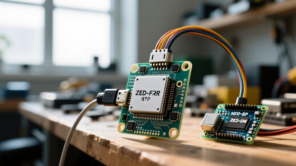
When upgrading your GPS receiver Arduino hardware, you generally have two modern pathways: a high-precision standard multi-band module, or a full dual-band RTK engine. Below is a comparison of the legacy standard versus the two most popular upgrade paths.
| Module | Frequency Bands | Standalone Accuracy | Primary Interface | Approx. Cost (USD) |
|---|---|---|---|---|
| NEO-6M (Legacy) | L1 Only | ~2.5 meters | UART (9600 baud) | $10 - $15 |
| SAM-M10Q (Modern) | L1/L2/L5/B1/B2 (4-Band) | ~1.5 meters | UART / I2C (DDC) | $25 - $35 |
| ZED-F9P (RTK) | Dual-Band (L1/L2) | 0.01 meters (with RTK) | UART / I2C / SPI | $150 - $220 |
For projects requiring sub-meter accuracy without the need for a base station, the SAM-M10Q is a massive leap forward, utilizing concurrent reception of four GNSS constellations to eliminate multipath errors. However, if your project demands centimeter-level precision for rover navigation or automated steering, the ZED-F9P is the mandatory upgrade choice.
Power and Antenna Considerations for Upgraded Modules
A critical failure mode during migration is underestimating the power draw of next-generation modules. The NEO-6M typically draws around 45mA during tracking. In contrast, the ZED-F9P can draw upwards of 75mA during standard tracking, and spike to 150mA or more during initial satellite acquisition or when processing RTCM correction data.
The standard 3.3V regulator on an authentic Arduino Uno R3 is only rated for ~150mA total, and it must also supply the ATmega16U2 USB interface chip. Connecting a ZED-F9P directly to the Uno's 3.3V pin will almost certainly cause brownouts and I2C bus lockups. Migration Rule: Always use a dedicated buck converter (like a Pololu 3.3V step-down) powered from the Arduino's 5V or VIN pin to supply the GNSS module independently.
Additionally, RTK modules require high-quality active antennas with built-in Low Noise Amplifiers (LNAs). Ensure your carrier board routes the 3.3V VCC_RF line to the antenna connector to power the LNA; a passive patch antenna will render the RTK engine completely blind to the secondary L2 frequency.
Rewiring the Arduino: UART vs. I2C (Qwiic) Topologies
Legacy GPS setups almost universally relied on SoftwareSerial on digital pins 10 and 11. This is a blocking, CPU-intensive process that fails reliably above 38400 baud. When migrating to a ZED-F9P or SAM-M10Q, you must abandon SoftwareSerial entirely.
You have two robust migration paths for wiring:
- Hardware UART (Serial1): Ideal for Arduino Mega, Teensy, or ESP32 boards. You wire the module's TX/RX to the microcontroller's dedicated hardware serial pins. This offloads byte-level parsing to the UART interrupt handler.
- I2C (u-blox DDC): The preferred method for modern I2C ecosystems (like SparkFun's Qwiic or Adafruit's STEMMA QT). I2C allows you to daisy-chain the GPS receiver with IMUs and magnetometers on the same bus.
Crucial I2C Gotcha: The ZED-F9P's I2C interface is sensitive to bus capacitance. Most breakout boards include 2.2kΩ pull-up resistors. If you are daisy-chaining multiple sensors on the same I2C bus, the parallel resistance will drop too low, corrupting the data lines. You must use a jumper cutter to disable the pull-ups on all but one device on the bus, or use a dedicated I2C bus multiplexer like the TCA9548A.
Software Migration: Transitioning from TinyGPS++ to UBX Binary
The most profound software change in your GPS receiver Arduino upgrade is moving away from NMEA text parsing. To achieve RTK fix status, the module must output carrier-phase measurements, which are not supported by standard NMEA sentences. You must configure the module to output the proprietary UBX binary protocol.
While the SparkFun u-blox GNSS Arduino Library is the industry standard for this migration, understanding the underlying data shift is vital for optimizing your sketch.
Handling Baud Rates and I2C Clock Speeds
An NMEA stream at 10Hz updates can easily saturate a 9600 baud serial connection. By migrating to UBX binary over I2C, you change the paradigm entirely. Instead of the module 'pushing' a continuous stream of text, the Arduino 'pulls' specific binary packets (like UBX-NAV-PVT) exactly when needed.
// Legacy NMEA Pull (SoftwareSerial)
while (ss.available() > 0) {
  gps.encode(ss.read());
}

// Modern UBX I2C Pull (SparkFun Library)
if (myGNSS.getPVT()) {
  double latitude = myGNSS.getLatitude() / 10000000.0;
  double longitude = myGNSS.getLongitude() / 10000000.0;
  uint8_t fixType = myGNSS.getFixType(); // 0=No fix, 3=3D, 4=RTK Fix, 5=RTK Float
}
When using I2C, ensure you explicitly set the Wire clock speed. The ZED-F9P supports I2C Fast Mode (400kHz). Add Wire.setClock(400000); in your setup() function immediately after Wire.begin() to prevent the I2C bus from becoming a bottleneck during high-rate RTK corrections.
Real-World Troubleshooting: Common Upgrade Pitfalls
Migrating to high-precision GNSS is rarely plug-and-play. Here are the most common failure modes encountered during field testing:
The I2C Stretch Lockup: The ZED-F9P features an internal RTK engine that occasionally requires heavy processing cycles, particularly when first receiving RTCM correction messages from a base station. During these cycles, the module will 'stretch' the I2C clock signal. Older 8-bit Arduino Wire libraries do not handle clock stretching gracefully, resulting in a hard lockup of the microcontroller. If your Arduino freezes exactly 30 seconds after turning on (when the first RTK corrections arrive), drop the I2C clock to 100kHz or switch to Hardware UART.
Another frequent issue involves the NTRIP correction pipeline. The ZED-F9P does not connect to the internet natively. To achieve RTK Fix status, your Arduino must fetch RTCM3 data from an NTRIP caster via a secondary connection (like an ESP32's WiFi or a 4G LTE modem) and push those bytes directly into the ZED-F9P's I2C or UART RX port. If the RTCM messages are delayed by more than a few seconds, the RTK engine will downgrade from a 'Fixed' solution to a 'Float' solution, degrading accuracy from 2cm back to 0.5 meters.
Final Calibration and Field Testing
Once your hardware is rewired and your software is migrated to the UBX protocol, the final step is field calibration. Mount your active multi-band antenna on a ground plane (a 10cm x 10cm sheet of aluminum or copper tape drastically improves L2 reception). Power up the system in an open sky environment and allow the module to download the latest almanac data. Monitor the getFixType() register; once you see a return value of 4 (RTK Fixed), your migration is complete, and your Arduino is now capable of professional-grade spatial awareness.