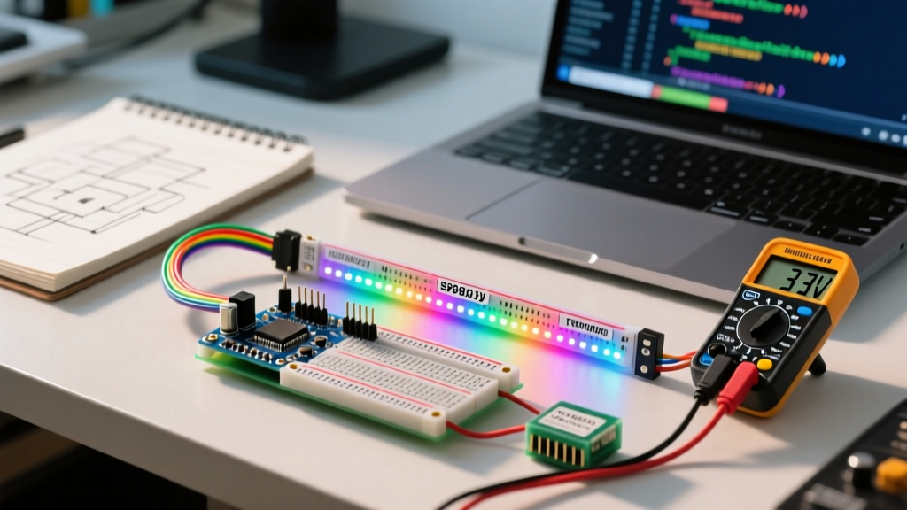

The Legacy Arduino NeoPixel Bottleneck
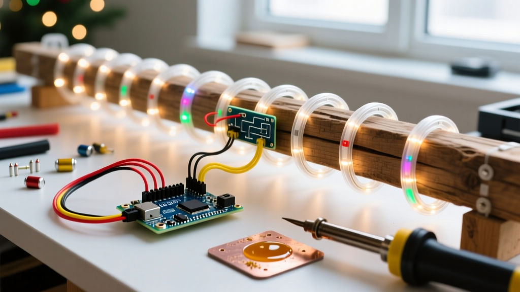
For years, the classic Arduino NeoPixel setup—an Arduino Uno paired with WS2812B LED strips and the Adafruit NeoPixel library—has been the gold standard for makers entering the world of addressable lighting. However, as we move through 2026, the limitations of 5V ATmega328P microcontrollers and standard RGB diodes have become glaringly apparent. Modern installations demand higher refresh rates, Wi-Fi/Bluetooth connectivity, and the pure white illumination that standard RGB strips simply cannot produce.
If you are looking to scale up your installation, integrate IoT controls via an ESP32 or RP2040, or achieve professional-grade lighting temperatures, a migration is mandatory. This guide provides a comprehensive, engineering-focused roadmap for upgrading your legacy Arduino NeoPixel ecosystem to modern SK6812 RGBW hardware, 3.3V logic architectures, and the high-performance FastLED library.
Hardware Evolution: WS2812B vs. SK6812 RGBW
The most impactful upgrade you can make is swapping the physical LED modules. The legacy WS2812B relies on three diodes (Red, Green, Blue) to mix colors. Attempting to create 'white' by maxing out all three channels results in a harsh, bluish-cyan tint and massive current spikes. The SK6812 RGBW solves this by integrating a dedicated phosphor-coated white diode.
| Specification | WS2812B (Legacy) | SK6812 RGBW (Upgrade) | Migration Impact |
|---|---|---|---|
| Diode Configuration | RGB (3-in-1) | RGBW (4-in-1) | True warm/cool white output |
| Max Current per Pixel | ~60mA | ~80mA | Requires heavier power wiring |
| Data Protocol Timing | T0H: 0.4µs / T1H: 0.8µs | T0H: 0.3µs / T1H: 0.6µs | Requires FastLED RGBW controller |
| Average Cost (5m Strip, 60LED/m) | $12.00 - $15.00 | $18.00 - $24.00 | Higher initial BOM cost |
When purchasing SK6812 strips, pay strict attention to the white color temperature. They are commonly available in 3000K (Warm), 4500K (Neutral), and 6000K (Cool). For indoor architectural lighting or under-cabinet maker projects, 3000K or 4500K is highly recommended to avoid the clinical look of 6000K.
The 3.3V Logic Level Trap (And How to Fix It)
The most common point of failure when migrating from a 5V Arduino Uno to a modern 3.3V microcontroller (like the ESP32-S3 or Raspberry Pi Pico) is data line voltage degradation. According to the Adafruit NeoPixel Überguide, the WS2812B and SK6812 data sheets specify a minimum logic HIGH threshold (Vih) of 0.7 x VDD. If your strip is powered by 5V, the data line must reach at least 3.5V to be reliably read as a '1'.
A 3.3V microcontroller GPIO pin outputs a maximum of 3.3V. While some modern LED batches will tolerate this marginal voltage, it inevitably leads to the 'first pixel flicker' or random color shifting down the line.
The Solution: SN74AHCT125 Level Shifter
Do not rely on software workarounds or simple transistor inverters. The industry-standard solution for high-speed NeoPixel data lines is the SN74AHCT125 quad bus buffer IC. The AHCT logic family is specifically designed to accept 3.3V inputs while powered by 5V, outputting a clean, sharp 5V square wave capable of keeping up with the 800kHz NeoPixel data rate.
Wiring the 74AHCT125:
1. Connect VCC (Pin 14) to your 5V LED power supply.
2. Connect GND (Pin 7) to the common ground.
3. Connect your ESP32/RP2040 GPIO (Data Out) to 1A (Pin 2).
4. Connect 1Y (Pin 3) to the LED strip DIN (Data In) via a 330Ω resistor.
5. Tie the 1OE (Output Enable, Pin 1) to GND to permanently enable the buffer.
For a deep dive into the timing tolerances of this specific IC family, refer to the Texas Instruments SN74AHCT125 datasheet and product overview.
Software Migration: Adafruit NeoPixel to FastLED
The Adafruit NeoPixel library is fantastic for beginners, but it relies on 'bit-banging'—disabling all microcontroller interrupts to manually time the GPIO toggles. On an ESP32 handling Wi-Fi stacks or audio processing, this causes massive latency and network drops.
Migrating to FastLED is non-negotiable for advanced 2026 projects. FastLED utilizes hardware DMA (Direct Memory Access) and SPI/I2S peripherals on modern MCUs, pushing LED data in the background without blocking the main CPU loop.
Code Translation for RGBW
FastLED natively supports RGBW strips, but you must explicitly define the controller type. Replace your legacy initialization with the following architecture:
#define LED_PIN 16
#define NUM_LEDS 144
CRGBW leds[NUM_LEDS];
// In setup():
FastLED.addLeds
Note: Because FastLED's native RGBW implementation maps memory differently, always verify your strip's specific color order (GRB vs RGB) and adjust the template parameters accordingly.
Power Injection and Topology for High-Count Arrays
Upgrading to RGBW increases your maximum current draw by 33%. A standard 5-meter strip of 60 LEDs/m (300 LEDs total) will pull 24 Amps at maximum white brightness (300 x 80mA). Relying on a single USB barrel jack or thin ribbon cables will result in severe voltage drop, causing the end of the strip to glow dimly and shift to pink/red.
The 3-Amp Rule and Wire Sizing
Never push more than 3 Amps through a single injection point on the strip's internal PCB traces. For a 24A system, you must inject power at both ends of the strip, and ideally every 2 meters in between.
- 18 AWG Silicone Wire: Safe for up to 5A per run (use for short jumper injections).
- 14 AWG Copper Wire: Safe for up to 15A per run (use for main bus lines from the PSU).
- 10 AWG Copper Wire: Required for the primary connection between a high-wattage PSU and the distribution terminal block.
Always place a 1000µF to 2200µF, 6.3V (or 10V) electrolytic capacitor directly across the VCC and GND terminals at your first injection point. This acts as a local energy reservoir to smooth out the massive transient current spikes that occur when the entire strip flashes white simultaneously, protecting your power supply from tripping its over-current protection.
Essential 2026 Bill of Materials (BOM)
To execute this migration properly, source the following specific components:
- Microcontroller: ESP32-S3-DevKitC-1 (Dual-core, native USB, ample DMA channels) — ~$8.00
- LED Strip: BTF-Lighting SK6812 RGBW 3000K (5m, 60 LEDs/m, IP30) — ~$22.00
- Logic IC: SN74AHCT125N (DIP-14 package for easy breadboard/protoboard soldering) — ~$0.90
- Power Supply: Mean Well LRS-350-5 (5V 70A, enclosed) or LRS-35-5 (5V 7A for small builds) — ~$18.00 - $45.00
- Passives: 1/4W 330Ω Carbon Film Resistors (Data line) & 2200µF 10V Capacitors — ~$4.00
Advanced Troubleshooting FAQ
Why does my ESP32 flash all LEDs bright white on boot?
This is a notorious hardware strapping issue. On the original ESP32, GPIO12 is a strapping pin for flash voltage. If it is pulled high by the LED strip's data line during boot, the ESP32 may enter a fail-safe mode or output a transient HIGH signal. Fix: Move your data pin to GPIO16, GPIO17, or GPIO18, and add a 10kΩ pull-down resistor between the data pin and GND to keep the line low during the boot sequence.
My FastLED code compiles, but the colors are scrambled (Red is Green, White is Pink).
SK6812 strips are manufactured in different color orders. While WS2812B is almost universally GRB, SK6812 RGBW strips frequently use GRBW or RGBW byte orders. If your white channel is mixing incorrectly or colors are swapped, change the FastLED template definition from GRB to RGB or utilize the SK6812RGBW specific enum in the latest FastLED 3.6+ branches.
Can I use a MOSFET to switch the ground line for power saving?
No. Addressable LEDs require a constant, stable ground reference for the data signal to be interpreted correctly. If you switch the ground line via a MOSFET while the data line remains active, the internal logic ICs inside the LEDs will attempt to ground themselves through the data pin, potentially destroying the first few pixels in the chain. Always switch the 5V VCC line using a high-side P-Channel MOSFET or a dedicated relay if you must cut power.