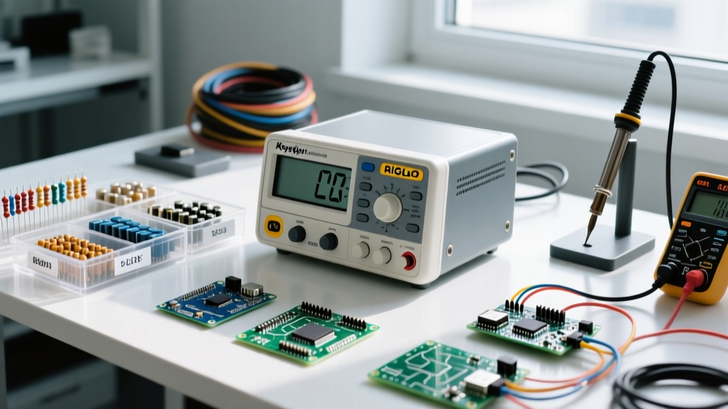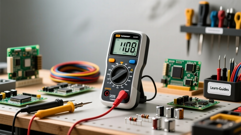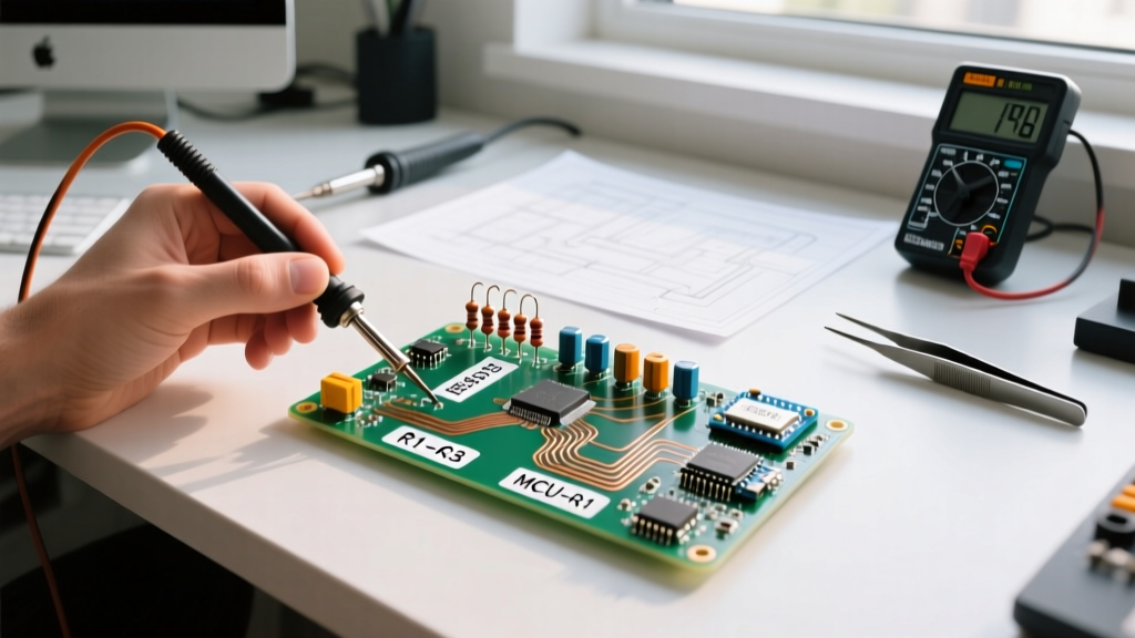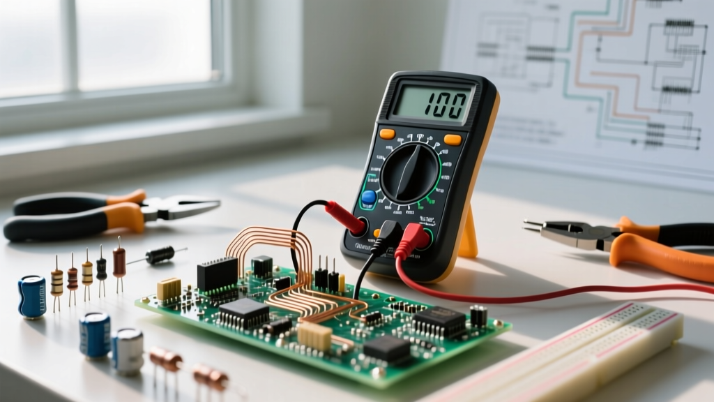

Learning how to test voltage with a multimeter is the foundational milestone in any electrical or electronics skill-building path. Voltage, measured in volts (V), represents the electrical potential difference or 'pressure' pushing current through a circuit. Whether you are debugging an Arduino prototype, troubleshooting a residential HVAC control board, or verifying mains power at a breaker panel, accurate voltage measurement is non-negotiable. This guide is structured as a progressive skill-building path, taking you from basic DC measurements to advanced AC troubleshooting, complete with real-world failure modes and safety protocols.
Phase 1: Understanding IEC 61010 Safety Categories
Before you ever touch a probe to a live circuit, you must understand the environment you are working in. The International Electrotechnical Commission (IEC) establishes safety standards for test equipment, known as Measurement Categories (CAT). According to Fluke's Guide to Safety Ratings, using a meter with an inadequate CAT rating in a high-energy environment can result in catastrophic arc flashes.
- CAT II: Single-phase receptacle connected loads (e.g., testing a household appliance or a desktop PC power supply).
- CAT III: Three-phase distribution, including single-phase commercial lighting and hardwired equipment (e.g., testing a 240V dryer outlet or an industrial motor contactor).
- CAT IV: Three-phase utility connections and outdoor service entrances (e.g., testing at the main breaker panel or utility meter base).
Expert Insight: Never use a cheap, unbranded $15 multimeter for CAT III or CAT IV work. Quality meters from brands like Fluke or Brymen use HRC (High Rupturing Capacity) ceramic fuses filled with sand to quench internal arcs if you make a mistake. Cheap meters use standard glass fuses that can literally explode inside the casing during a high-energy fault.
Phase 2: The Core Mechanics of DC Voltage Testing
Direct Current (DC) voltage flows in a single direction, typical of batteries, solar panels, and microcontroller logic rails. To begin your skill-building path, master DC testing on low-energy circuits.
Step-by-Step DC Measurement
- Probe Placement: Insert the black probe into the COM (common) jack. Insert the red probe into the V/Ω jack. Warning: Never leave the red probe in the 'A' or '10A' current jack when measuring voltage. This creates a dead short across your power source.
- Dial Selection: Turn the dial to the DC Voltage setting (denoted by a 'V' with a solid line and dashed line beneath it). If your meter is manual-ranging, select a range higher than your expected voltage. For a 9V battery, select the 20V range.
- Measurement: Touch the black probe to the negative terminal (ground) and the red probe to the positive terminal.
If you see a negative sign (e.g., -5.02V) on a digital display, it simply means your probe polarity is reversed relative to the circuit's ground. As noted in the SparkFun Multimeter Tutorial, digital multimeters (DMMs) handle reversed polarity gracefully, unlike analog needle meters which will peg the needle backward and potentially damage the movement.
Phase 3: Tackling AC Voltage and Ghost Reads
Alternating Current (AC) voltage periodically reverses direction. Testing 120V or 240V mains requires heightened awareness and an understanding of how multimeters calculate AC waveforms.
True-RMS vs. Average-Responding
Standard AC voltage in the US is a sine wave peaking at roughly 170V but delivering an effective 'heating' voltage of 120V. This effective value is the Root Mean Square (RMS). Basic multimeters use an 'average-responding' circuit that assumes a perfect sine wave. However, modern electronics (LED drivers, variable frequency drives, switching power supplies) distort the sine wave. An average-responding meter can read up to 30% low on these non-linear loads. To build advanced troubleshooting skills, you must invest in a True-RMS multimeter, which samples the waveform thousands of times per second to calculate the actual heating value regardless of distortion.
Eliminating Phantom Voltage with LoZ
When testing multi-conductor cables (like 14/3 Romex), you may measure 40V to 80V on a disconnected 'dead' wire. This is phantom voltage caused by capacitive coupling from an adjacent live wire. Advanced meters feature a LoZ (Low Impedance) mode. Standard DMMs have an input impedance of 10 Megohms, which is sensitive enough to read this coupled ghost voltage. LoZ mode drops the impedance to roughly 3 kilohms, bleeding off the capacitive charge and displaying the true 0V state of the dead wire.
Phase 4: Multimeter Feature Comparison for Voltage Testing
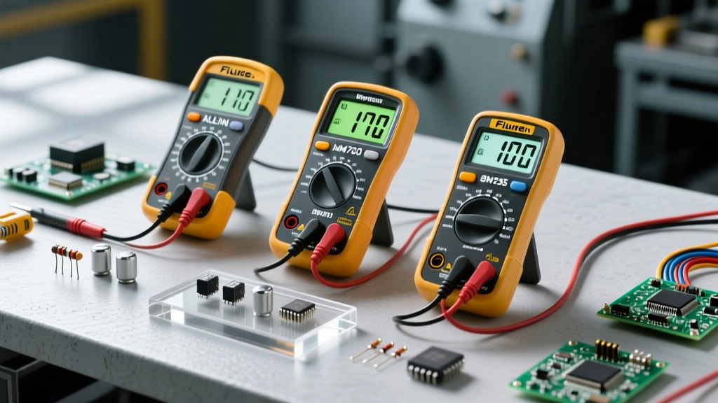
Choosing the right tool accelerates your skill-building path. Below is a comparison of three popular multimeters tailored to different voltage testing needs.
| Model | Approx. Price | True-RMS | LoZ Mode | Safety Rating | Best Use Case |
|---|---|---|---|---|---|
| Klein Tools MM400 | $45 - $55 | No (Average) | No | CAT III 600V | Beginner DC electronics, basic home DIY |
| Brymen BM235 | $110 - $130 | Yes | Yes | CAT III 600V / CAT IV 300V | Advanced DIY, HVAC, automotive diagnostics |
| Fluke 117 | $180 - $210 | Yes | Yes (AutoVolt) | CAT III 600V | Professional electricians, industrial controls |
Phase 5: Advanced Troubleshooting and Fatal Errors
As you progress from a beginner to an advanced technician, you must learn to identify multimeter failure modes and user errors that compromise voltage readings or destroy equipment.
The 'Amps Port' Catastrophe
The most common fatal error in voltage testing is leaving the red probe in the Amperage (A) jack. The current measurement circuit relies on an internal shunt resistor with near-zero resistance (often less than 0.1 ohms) to measure the voltage drop across it. If you connect this near-zero resistance path across a 120V AC mains outlet or a high-current DC battery bank, you are creating a dead short. The resulting current spike will instantly vaporize the internal shunt or blow the HRC fuse with a violent pop. Always visually verify your probe jacks before turning the dial to Voltage.
Low Battery Indicators and ADC Drift
Modern DMMs use an internal Analog-to-Digital Converter (ADC) and a precision voltage reference IC to calculate readings. When the 9V or AA batteries inside the meter drop below a critical threshold, the voltage reference becomes unstable. This causes the ADC to drift, resulting in wildly inaccurate voltage readings. As highlighted by All About Circuits, precision measurement requires stable internal references. If your meter displays a low battery icon, or if your readings fluctuate erratically on a known stable DC source (like a fresh 9V battery reading 9.4V one second and 7.2V the next), replace the batteries immediately before trusting the meter for critical troubleshooting.
Degraded Test Probes
Test probes are not lifetime accessories. The internal copper wire can fray near the strain relief, and the probe tips can become oxidized or coated in flux residue. Oxidation adds series resistance to your measurement path. While this series resistance won't heavily impact voltage readings (due to the meter's 10MΩ input impedance), it will completely ruin continuity and low-resistance measurements. Inspect your probe insulation for cracks before every CAT III or CAT IV voltage test to prevent lethal shock hazards.
Conclusion: Cementing Your Voltage Testing Skills
Mastering how to test voltage with a multimeter is not just about reading a digital display; it is about understanding the physics of the circuit, the limitations of your test equipment, and the safety parameters of your environment. By progressing through this skill-building path—from verifying basic DC polarity to utilizing True-RMS and LoZ modes for complex AC diagnostics—you transition from a passive observer to an active, analytical troubleshooter. Keep your probes in the correct jacks, respect the IEC safety categories, and always verify your meter on a known live source before diagnosing a dead circuit.