
The 2026 Landscape of BTC Electronic Component Diagnostics
As Bitcoin mining hardware evolves in 2026, power densities on hash boards have surged past 35W per chip in flagship models like the Antminer S21 Pro and MicroBT Whatsminer M60. This extreme operational stress drastically reduces the lifespan of BTC electronic components, specifically the Power Management ICs (PMICs), buck converter stages, and the ASIC chips themselves. For electronics technicians and DIY repair specialists, mastering component-level diagnostics on these 6-to-8-layer PCBs is one of the most lucrative skill paths available today.
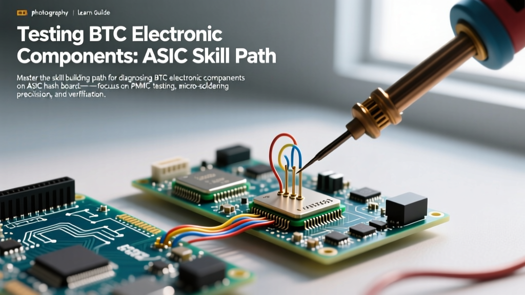
Unlike standard consumer electronics, hash boards utilize massive copper ground planes and heavy-duty alloy shunt resistors that act as enormous heat sinks. This structural reality means that standard soldering and multimeter techniques must be heavily adapted. This guide outlines a comprehensive, four-phase skill-building path to diagnose, trace, and replace BTC electronic components with precision.
Phase 1: Anatomy of the ASIC Power Stage
Before applying a multimeter probe, you must understand the topology of a modern hash board power domain. Each ASIC chip (e.g., Bitmain BM1368 or MicroBT BT33) requires a highly regulated core voltage (Vcore), typically between 0.38V and 0.45V, delivered at massive currents (often exceeding 150A per domain).
- PMIC / Buck Controllers: Multi-phase synchronous buck controllers (such as the Texas Instruments TPS546D24A or similar custom ASICs) step down the 12V-15V input from the Power Supply Unit (PSU).
- MOSFETs: High-side and low-side MOSFETs switch at frequencies upwards of 1MHz to maintain tight transient response.
- Shunt Resistors: 0.5mΩ to 1mΩ surface-mount alloy resistors are placed in series with the inductor to provide current feedback to the PMIC.
According to data from the Cambridge Centre for Alternative Finance (CCAF), the global push for energy efficiency in mining means that minor voltage deviations caused by failing BTC electronic components will immediately trigger a hash board's protective shutdown sequence, resulting in 'Missing Chips' or 'Zero Hashrate' errors in the miner's web interface.
Phase 2: Cold Testing and Short-Circuit Isolation
The first step in the skill-building path is 'cold testing'—measuring resistance and diode drops while the board is entirely unpowered. This requires a high-precision multimeter, such as the Fluke 87V, capable of resolving milliohm variations.
Step-by-Step Cold Diagnostics
- Vcore Ground Short Check: Set your multimeter to continuity/resistance mode. Place the black probe on a known ground (e.g., the metal chassis mounting hole) and the red probe on the output inductor of the buck converter. A healthy reading should be between 2Ω and 15Ω, slowly rising as capacitors charge. A reading below 0.5Ω indicates a dead short, usually a failed low-side MOSFET or a fractured ceramic decoupling capacitor.
- Shunt Resistor Verification: Switch to the milliohm range. Measure across the current sense resistor. If a 0.5mΩ resistor reads open (OL) or significantly higher (e.g., 5mΩ), the solder joints have cracked due to thermal cycling—a very common failure mode in BTC electronic components.
- MOSFET Diode Mode Testing: As outlined in Fluke's official testing guidelines, use diode mode to check the intrinsic body diode of the MOSFETs. A reading of 0.000V across Drain and Source confirms a blown MOSFET, which will instantly short the 12V rail to ground upon boot.
Modern hash boards feature massive input filter capacitor banks (often 1000µF+ at 25V). Before performing cold tests, always bridge the input terminals with a 100Ω 5W power resistor to safely bleed off residual charge. Shorting them with a screwdriver can vaporize PCB traces and destroy your multimeter's internal fuse.
Phase 3: Hot Diagnostics and Signal Tracing
If cold tests pass but the board still throws a 'Domain Missing' error, the fault lies in the logic or signal lines. This requires an oscilloscope (like the Rigol DS1054Z) to inspect the communication buses.
Tracing the I2C and Clock Signals
ASIC chips communicate their status via an I2C bus and require a precise 25MHz clock signal to initiate hashing. When a single chip in a daisy-chain fails, it breaks the signal path for all subsequent chips.
- Clock Signal Verification: Probe the CLK pin on the first ASIC. You should see a clean, 3.3V peak-to-peak square wave at exactly 25.000MHz. If the signal degrades into a sine wave or drops in amplitude by the 15th chip, you have identified the failing component breaking the transmission line.
- I2C Bus Pull-ups: Measure the SDA and SCL lines. They must idle at 3.3V. If a line is pulled down to 0V, a specific ASIC chip has suffered an internal logic short and is holding the bus hostage. Isolate chips by carefully lifting the SDA pin with a hot air station until the bus voltage recovers.
PMIC Diagnostic Matrix: Common Failure Modes
Use this reference table when diagnosing power stage anomalies on BTC hash boards. These values represent standard operating parameters for 2026-era high-efficiency mining rigs.
| Component | Test Mode | Expected Reading | Failure Indicator |
|---|---|---|---|
| Buck Inductor (150nH) | Resistance | 0.2Ω - 0.8Ω | OL (Open winding) or 0.0Ω (Internal short) |
| High-Side MOSFET | Diode Mode (D-S) | 0.350V - 0.500V | 0.000V (Blown junction) |
| Current Sense Resistor | Milliohm Range | 0.5mΩ ± 1% | < 0.4mΩ or > 2.0mΩ (Thermal cracking) |
| PMIC Enable (EN) Pin | DC Voltage (Hot) | 1.2V - 3.3V | 0V (Microcontroller withholding enable signal) |
Phase 4: Advanced Micro-Soldering on High-Mass PCBs
Replacing BTC electronic components is not like swapping a capacitor on a laptop motherboard. Hash boards utilize thick copper layers (often 2oz to 4oz internal planes) designed specifically to dissipate hundreds of watts of heat. If you attempt to desolder a PMIC or an ASIC chip with a standard hand iron, you will experience severe 'wicking' and pad lifting, permanently destroying the board.
The Pre-Heat Requirement
To achieve a successful rework, you must elevate the ambient temperature of the entire PCB section. Following the thermal management principles outlined in IPC-7711/7721 standards for electronic rework, use a dedicated PCB pre-heater (such as the Quick 853A) set to 150°C - 160°C. This reduces the thermal delta between your hot air nozzle and the board, preventing localized warping.
Execution Protocol for ASIC Replacement
- Flux Application: Apply a generous amount of high-tack, no-clean tacky flux (e.g., Amtech NC-559-V2-TF) under the chip edges. Do not use liquid rosin flux, as it will boil and displace the component during reflow.
- Thermal Profiling: Use a hot air rework station (e.g., Quick 861DW) with a 12mm round nozzle. Set the temperature to 380°C and airflow to 40%. Heat the chip in a continuous circular motion for 60-90 seconds. Never hold the nozzle stationary.
- Extraction: Once the solder melts (indicated by the chip 'floating' when nudged gently with tweezers), lift the chip vertically. Do not drag it, or you will shear the micro-pads.
- Pad Preparation: Clean the residual solder using a desoldering wick (Chemtronics 2mm) and a high-thermal-mass chisel tip iron (Hakko FX-951 with a C4 tip) set to 360°C. The iron must have enough thermal mass to overcome the ground plane's heat dissipation.
- Reballing and Seating: For BGA ASIC chips, use a direct-heat reballing stencil with 63/37 leaded solder paste. Leaded solder (melting point 183°C) is highly recommended for rework over lead-free (SAC305) because it reduces thermal stress on the aging PCB substrate and offers superior resistance to the extreme thermal cycling inherent in mining environments.
Conclusion: Building Long-Term Diagnostic Intuition
Mastering the repair of BTC electronic components is a journey of pattern recognition. By rigorously applying cold-testing methodologies, understanding the nuances of high-current buck converters, and respecting the thermal mass of mining PCBs, you transition from a parts-swapper to a true diagnostic technician. Keep your multimeter calibrated, maintain your oscilloscope probes, and always document your baseline resistance readings for new board revisions as they enter the market.