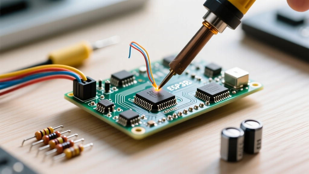

The Metallurgy of Wire: Why Material Dictates Your Approach
At its core, soldering is a metallurgical bonding process, not merely a mechanical one. When you ask how to solder two wires together, the answer fundamentally depends on the base metal's oxidation rate, thermal conductivity, and the insulation's thermal tolerance. Copper is the undisputed king of electrical wiring due to its low resistivity and ease of soldering. However, modern electronics, automotive harnesses, and aerospace applications frequently utilize aluminum for weight savings, or high-temperature alloys for extreme environments. Understanding the metallurgical barriers—such as aluminum's instantaneous formation of a non-conductive oxide layer—is the difference between a high-reliability joint and a catastrophic field failure. This material-specific guide will walk you through the exact thermal profiles, flux chemistries, and mechanical preparation techniques required for every wire type you might encounter on your workbench.
The Universal Baseline: How to Solder Two Wires Together
Before diving into material-specific anomalies, we must establish the universal baseline for wire splicing. Solder is not a conductive glue; it is a metallurgical bridge. Therefore, the mechanical connection must bear the physical load before the iron ever touches the wire.
- Stripping and Cleaning: Remove exactly enough insulation to allow for the chosen splice. For stranded wire, ensure no copper strands are nicked during stripping, as this reduces the tensile strength and creates localized hotspots.
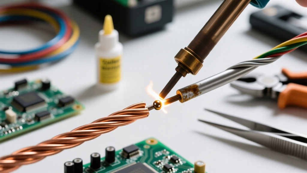
- Twisting and Splicing: For solid core wire, the Western Union (Lineman's) splice provides exceptional tensile strength. For stranded wire, an inline splice or a hook splice is preferred to prevent the wire from fraying.
- Pre-tinning (Optional but Recommended): Applying a small amount of solder to each individual wire before joining them ensures that capillary action will pull the solder deep into the strands during the final joint.
- Heat Application and Flow: Apply the iron to the wire, not the solder. The wire must reach the eutectic melting point of your alloy before introducing the solder to the opposite side of the joint.
- Cooling: Allow the joint to cool naturally. Blowing on the joint or moving the wire during the plastic (semi-solid) phase of the cooling curve will result in a disturbed, high-resistance cold joint.
Material-Specific Protocols and Temperature Profiles
Bare and Tinned Copper
Copper is highly receptive to standard rosin-based fluxes. If you are working with pre-tinned copper wire, the tinning process has already protected the base metal from oxidation, meaning you can often use a mild No-Clean flux or rely entirely on the flux core inside your solder wire. For bare copper, a mildly activated rosin flux (RMA) is ideal to strip away surface copper oxide (CuO). The optimal temperature profile for standard 60/40 (Sn60/Pb40) leaded solder on copper is between 320°C and 350°C. If you are using lead-free SAC305 (Tin/Silver/Copper), you must increase your iron temperature to 360°C - 380°C to account for the alloy's higher melting point (217°C vs 183°C) and poorer wetting characteristics. Always refer to Hakko's thermal recovery guidelines to ensure your station can maintain these temperatures under load without dropping into a cold-joint risk zone.
The Aluminum Challenge: Oxide Layers and Specialized Flux
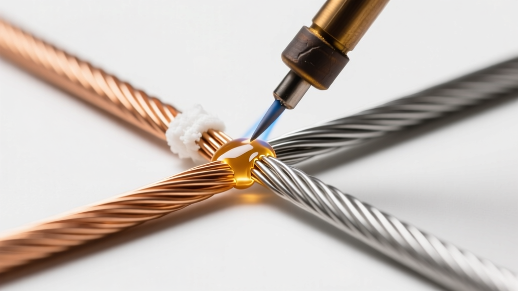
Soldering aluminum wire is notoriously difficult and is heavily restricted in high-reliability applications under the IPC J-STD-001 standard. The core issue is aluminum oxide (Al2O3). While pure aluminum melts at a relatively low 660°C, its oxide layer melts at an astonishing 2072°C. Standard rosin fluxes cannot dissolve this ceramic-like barrier. If you attempt to solder aluminum with standard gear, the solder will simply ball up and roll off.
To successfully solder aluminum wire, you must use one of two methods:
- Chemical Fluxing: You must use a highly aggressive Zinc Chloride or Ammonium Fluoride-based flux specifically designed for aluminum. These fluxes chemically etch away the oxide layer. However, they are highly corrosive and must be meticulously cleaned with isopropyl alcohol and a brush immediately after soldering to prevent long-term galvanic corrosion.
- Mechanical Abrasion: In a pinch, you can use a specialized aluminum solder wire (which often contains trace amounts of zinc and cadmium) and physically scratch the surface of the aluminum wire with a stainless steel pick while the iron is heating it. This breaks the oxide layer in an oxygen-deprived environment under the molten flux, allowing the solder to wet the bare aluminum.
- Ultrasonic Soldering: For professional aerospace applications, flux-less ultrasonic soldering irons are used. These irons vibrate at high frequencies, creating microscopic cavitation bubbles in the molten solder that literally blast the aluminum oxide layer away, allowing perfect metallurgical wetting without corrosive chemicals.
High-Temperature Insulations: PTFE and Silicone
When working with military-spec or high-end audio wire, you will frequently encounter PTFE (Teflon) or Silicone insulation. Unlike standard PVC, which melts and melts back rapidly at 350°C, PTFE and Silicone can withstand extreme heat. While this prevents insulation meltback, it creates a hidden danger: because the insulation doesn't melt, technicians tend to leave the iron on the wire far too long, attempting to force heat into heavy-gauge wire. This prolonged heating causes the copper deep inside the wire to oxidize, and can cause the flux core to burn out before the joint is complete. When working with PTFE, use a high-thermal-mass tip and aggressive heating to complete the joint in under three seconds, preserving the integrity of the copper strands beneath the indestructible jacket.
Thermal Mass: Adjusting for Wire Gauge (AWG)
Understanding how to solder two wires together also requires an understanding of thermal mass. A thick 10 AWG wire acts as a massive heat sink, pulling thermal energy away from your soldering iron tip faster than the station's heating element can replenish it. If you use a fine conical tip on a heavy wire, the tip temperature will plummet, resulting in a cold joint. You must match your tip geometry and temperature to the wire gauge.
| Wire Gauge (AWG) | Recommended Tip Shape | Target Temp (Sn60/Pb40) | Target Temp (SAC305 Lead-Free) | Thermal Mass Category |
|---|---|---|---|---|
| 24-28 AWG | Fine Conical or Micro-K | 300°C - 320°C | 350°C - 360°C | Low |
| 18-22 AWG | Standard K-Type (Knife) | 320°C - 340°C | 360°C - 380°C | Medium |
| 12-16 AWG | Wide Chisel (D-Type) | 350°C - 370°C | 380°C - 400°C | High |
| 8-10 AWG | Heavy Chisel / Spoon | 380°C - 400°C | 410°C+ | Extreme |
For extreme thermal mass scenarios (8 AWG or thicker), standard 40W-60W soldering stations will fail. You must step up to a 100W+ station with active tip sensing, or use a localized pre-heater to bring the ambient temperature of the copper wire up to 150°C before applying the iron.
Failure Mode Analysis: Wicking, Cold Joints, and Meltback
Even with the correct materials, improper technique leads to distinct failure modes. Recognizing these is critical for quality control.
- Solder Wicking: This occurs when capillary action pulls molten solder far up the wire strands and under the insulation. This creates a rigid, brittle section of wire right at the strain relief point. Under vibration, this stiffened section will act as a fulcrum and snap. To prevent wicking, use minimal solder, avoid excessive heat, and utilize a physical heat sink (like a hemostat clamped between the splice and the insulation) to stop the thermal transfer.
- Disturbed and Cold Joints: A proper eutectic solder joint should look shiny and smooth (for leaded) or uniformly matte/silky (for lead-free). If the joint looks grainy, frosted, or cracked, it was likely moved during the plastic phase of cooling, or the iron was not hot enough to properly flux the surface. This creates microscopic fissures that increase electrical resistance and generate heat under load.
- Flux Entrapment: When twisting stranded wires too tightly, you leave no room for the flux to escape or the solder to penetrate. The solder forms a shell around the outside, while corrosive flux remains trapped in the dry center of the splice, leading to internal green corrosion over time. Always leave a slight gap or use a looser hook splice to allow capillary flow.
Industry Standards and Essential Gear
For any professional or high-reliability DIY work, your process should align with established industry benchmarks. The Kester flux chemistry data sheets provide invaluable insights into selecting the right activator levels (Rosin, RMA, RA) based on the oxidation level of your specific wire batch. Furthermore, investing in a thermocouple tip tester is highly recommended. Soldering station dials are notoriously inaccurate; a dial set to 350°C might actually read 310°C at the tip due to sensor degradation or poor thermal coupling. By verifying your true tip temperature, you eliminate the guesswork from material-specific soldering, ensuring that whether you are joining delicate 26 AWG tinned copper or heavy 12 AWG bare wire, your metallurgical bond will withstand the test of time, current, and environment.