
Every electronics maker has experienced the frustration of wiring a variable resistor backward, resulting in a volume knob that acts in reverse or a motor controller that spikes to full speed on startup. When transitioning from physical breadboarding to reading professional blueprints, understanding the schematic symbol potentiometer is a critical milestone in project-based learning. This guide moves beyond basic definitions, teaching you how to decode standard symbols, map them to physical hardware like the Bourns 3852 series, and implement them in real-world DIY circuits.
Deconstructing the Schematic Symbol Potentiometer
At its core, a potentiometer is a three-terminal resistor with a sliding or rotating contact that forms an adjustable voltage divider. However, the way this is represented on paper varies depending on the engineering standard your schematic follows.
IEEE 315 vs. IEC 60617 Standards
In North America, the IEEE 315 standard dominates. The schematic symbol potentiometer under this standard features a zig-zag line representing the resistive carbon or cermet track, bisected by an arrow pointing inward. This arrow represents the wiper (terminal 2). The two ends of the zig-zag line represent terminals 1 and 3.
Conversely, the international IEC 60617 standard replaces the zig-zag with a simple rectangular box. The wiper arrow remains, but it often crosses the rectangle or points to its side. Recognizing both is essential when sourcing open-source hardware designs from global platforms like GitHub or GrabCAD.
Project Lab: Building a Variable Voltage Divider
Let us apply this symbol to a practical project: creating an adjustable analog reference voltage for a microcontroller ADC (Analog-to-Digital Converter). Suppose you are building a custom sensor calibration board and need a variable 0V to 3.3V reference from a 5V rail.
By wiring Terminal 1 to Ground (0V) and Terminal 3 to VCC (5V), the wiper (Terminal 2) outputs a variable voltage based on its physical position. The schematic will show the zig-zag or box bridging the power rails, with the wiper arrow routing to your microcontroller's ADC pin.
For instance, if you are using a 10kΩ Bourns 3852C potentiometer across a 5V rail, setting the wiper to the 30% physical rotation mark on a linear taper yields approximately 1.5V at the wiper pin. The math follows the standard voltage divider equation: V_out = V_in * (R2 / (R1 + R2)). This predictable behavior is why linear pots are the undisputed choice for analog sensor calibration.
Understanding Taper Notations
A crucial detail often missed by beginners is the taper type, which dictates how resistance changes relative to the shaft rotation. While the basic symbol remains the same, engineers often add annotations next to the symbol to specify the taper.
| Taper Type | Schematic Annotation | Physical Marking | Ideal Project Application |
|---|---|---|---|
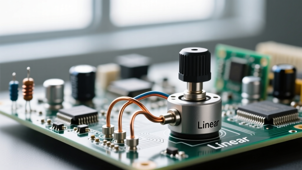
| Linear (B-Taper) | Often marked 'LIN' or a straight diagonal line across the symbol | B10k, 10KB | Sensor calibration, voltage dividers, motor speed control |
| Logarithmic (A-Taper) | Marked 'LOG' or a curved exponential line | A10k, 10KA | Audio volume controls (matches human hearing perception) |
| Reverse Log (C-Taper) | Rarely annotated, sometimes 'REV-LOG' | C10k, 10KC | Specialized audio fade-ins, specific synthesizer envelopes |
For our ADC calibration project, a 10kΩ Linear taper (like the Alpha 16mm B10K) is mandatory. Using a logarithmic taper here would result in a highly non-linear ADC response, making precise sensor calibration nearly impossible.
Rheostat Mode: Adapting the Symbol for Current Limiting
What happens when your schematic shows a potentiometer symbol, but only two wires are connected to it? This indicates the component is being used as a rheostat—a two-terminal variable resistor designed to limit current rather than divide voltage.
A classic project-based example is dimming a high-power LED array. By placing the rheostat in series with the LED and a DC power source, rotating the shaft increases the total circuit resistance, thereby dropping the current. According to the fundamental principles of potentiometers, the correct way to wire this in a physical circuit is to connect the wiper (Terminal 2) in series with the load, and tie one of the outer terminals (Terminal 1 or 3) directly to the wiper.
In high-current scenarios, such as controlling a 12V DC cooling fan, using a standard 1/4-watt carbon track potentiometer as a rheostat will result in thermal failure. The resistive track will literally burn open. For these project-based applications, you must select a wirewound potentiometer (often denoted by a specific wattage rating like 5W or 10W on the schematic) capable of dissipating the heat generated by I²R losses.
Pro-Tip: Never leave the unused outer terminal floating in a rheostat configuration. If the wiper experiences a momentary loss of contact with the resistive track due to vibration or oxidation, the circuit will open entirely. Tying the wiper to the unused terminal ensures that if the wiper lifts, the circuit simply defaults to the maximum resistance of the track, protecting your LEDs from sudden current spikes.
Verification: Multimeter Mapping to the Schematic
Before soldering a potentiometer to your custom PCB or permanent perfboard, you must verify its physical pinout against the schematic symbol. Manufacturers like Bourns and Alps do not universally standardize pin numbering across all form factors. Always consult the specific manufacturer datasheet for your exact part number.
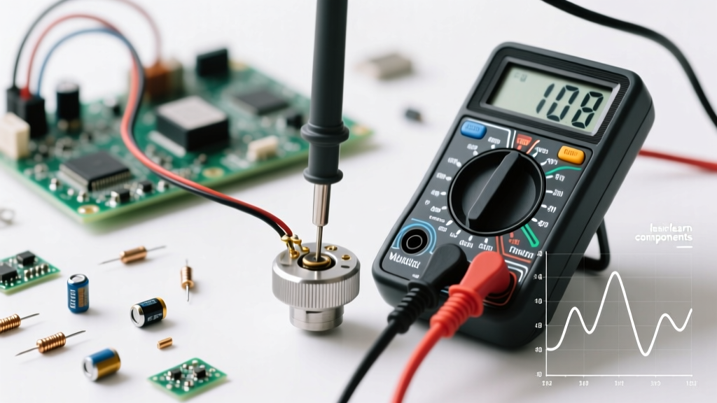
Follow this three-step multimeter verification process to ensure your physical hardware matches your schematic:
- Identify the Resistive Track (Terminals 1 & 3): Set your multimeter to resistance (Ohms). Place probes on the two outer pins. Rotate the shaft fully from end to end. The reading should remain static (e.g., exactly 10.2kΩ on a nominal 10kΩ pot). If it fluctuates, you have accidentally included the wiper pin.
- Locate the Wiper (Terminal 2): Keep one probe on a confirmed outer pin and move the second probe to the center pin. Rotate the shaft. The resistance should smoothly sweep from near 0Ω up to the total track resistance.
- Verify Taper Linearity: Set the potentiometer to the exact mechanical midpoint (using a dial indicator or visual marker on a smooth shaft). Measure between the wiper and Terminal 1. For a linear taper, it should read roughly 50% of the total resistance. If it reads 10% or 90%, you are holding an audio (logarithmic) taper.
Advanced Prototyping: Digital Potentiometers
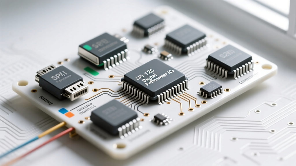
As your projects evolve from manual analog controls to automated digital systems, you will encounter digital potentiometers like the Microchip MCP41010. The schematic symbol for these components looks vastly different. Instead of a mechanical wiper arrow, the symbol features a standard resistor box with digital logic gates, SPI (Serial Peripheral Interface) lines (CS, SCK, SI), and a power bus.
Understanding the transition from the mechanical schematic symbol potentiometer to its digital counterpart allows you to seamlessly replace bulky mechanical knobs with software-driven resistance control in modern IoT devices, maintaining the same circuit logic while upgrading the user interface.
Mastering the reading and implementation of these symbols bridges the gap between abstract circuit theory and tangible, functional hardware. By rigorously verifying pinouts, respecting taper annotations, and utilizing rheostat fail-safes, your future DIY builds will be both robust and predictable.