
The Anatomy of Standard RGB LED Pins
When prototyping color-mixing circuits or building custom status indicators, identifying and wiring rgb led pins correctly is the first major hurdle. Unlike standard single-color LEDs that feature a simple two-leg anode-cathode configuration, standard 5mm through-hole RGB LEDs package three distinct semiconductor dies (Red, Green, and Blue) into a single epoxy dome. This necessitates a four-pin configuration to manage the electrical pathways for all three colors simultaneously.
However, not all four-pin configurations are created equal. The physical layout of rgb led pins generally follows a standard physical spacing (usually 1.27mm or 0.05-inch pitch between the outer pins, with a slightly wider gap or specific alignment for the common pin), but the internal electrical topology dictates how you must wire them to your microcontroller. Misidentifying the topology will result in inverted logic, short circuits, or completely dark pixels. To make the right component choice for your PCB or breadboard, we must compare the two primary analog alternatives—Common Anode and Common Cathode—against the modern digital alternative: Addressable RGB LEDs.
Head-to-Head: Common Anode vs. Common Cathode Pinouts
The most critical distinction in traditional rgb led pins is whether the three internal dies share a common positive connection (Anode) or a common negative connection (Cathode). This fundamental difference completely flips your firmware logic and hardware wiring.
| Feature | Common Anode (CA) | Common Cathode (CC) |
|---|---|---|
| Common Pin Connection | VCC (5V or 3.3V) | GND (0V) |
| Color Pin Logic | Active LOW (Sink Current) | Active HIGH (Source Current) |
| Longest Pin (Typical) | Common Anode (Pin 2) | Common Cathode (Pin 2) |
| Standard Pin Order | Red, Common, Green, Blue | Red, Common, Green, Blue |
| PWM Fading Behavior | 0% Duty Cycle = Full Brightness | 100% Duty Cycle = Full Brightness |
| Microcontroller Preference | Legacy TTL / 8051 / PIC | Arduino / ESP32 / Modern CMOS |
In a Common Cathode (CC) setup, the longest pin (usually the second pin from the left when viewing the LED from the bottom with the flat edge facing you) connects to ground. To illuminate the red die, you apply a positive voltage to the red pin. This aligns perfectly with modern microcontrollers like the Arduino or ESP32, where writing HIGH to a GPIO pin turns the color on.
Conversely, Common Anode (CA) LEDs are frequently found in legacy designs, automotive dashboards, and specific optocoupler circuits. The common pin is tied to VCC. To turn on a color, the microcontroller must pull the specific color pin to LOW, allowing current to flow through the die to ground. If you attempt to use Common Cathode logic on a Common Anode LED, your color mixing will be entirely inverted (e.g., trying to make white light will result in the LED turning off).
Resistor Selection and Forward Voltage Discrepancies
A frequent mistake when wiring rgb led pins is using a single identical current-limiting resistor for all three color legs. Because the three dies are manufactured from different semiconductor materials, their forward voltages (Vf) vary drastically. According to SparkFun's Comprehensive LED Tutorial, ignoring these discrepancies leads to severe color imbalance.
- Red Die (AlInGaP): Typical Vf is 2.0V to 2.2V.
- Green Die (InGaN): Typical Vf is 3.0V to 3.2V.
- Blue Die (InGaN): Typical Vf is 3.0V to 3.4V.
If you are driving a Common Cathode RGB LED from a 5V Arduino pin at a target current of 20mA, applying Ohm's Law (R = (Vs - Vf) / I) reveals the necessary resistor values:
- Red Resistor: (5V - 2.0V) / 0.02A = 150Ω
- Green Resistor: (5V - 3.2V) / 0.02A = 90Ω (Use 100Ω standard)
- Blue Resistor: (5V - 3.2V) / 0.02A = 90Ω (Use 100Ω standard)
If you mistakenly use a 150Ω resistor on the blue and green pins, they will be noticeably dimmer than the red pin, making it impossible to calibrate a true white or warm-yellow output. Always use independent resistors for each color pin.
Addressable Alternatives: WS2812B and SK6812 Data Pins
While standard 4-pin RGB LEDs are excellent for simple indicators, they require three separate PWM-capable microcontroller pins per LED. If your project requires a strip or matrix of 60 LEDs, you would need 180 GPIO pins—a physical impossibility for most boards. This is where addressable alternatives completely change the pinout paradigm.
Addressable LEDs, such as the ubiquitous WS2812B (NeoPixel) or the RGBW SK6812, integrate a control IC (like the WS2811) directly into the SMD package. Instead of analog color pins, these components utilize digital serial communication.
The WS2812B 4-Pin SMD Layout
Unlike the through-hole analog variants, the SMD 5050 package of a WS2812B features four distinct pads:
- VDD (Pin 1): Power supply (typically 5V).
- DOUT (Pin 2): Data output to the next LED in the chain.
- GND (Pin 3): Ground reference.
- DIN (Pin 4): Data input from the microcontroller or previous LED.
As detailed in the Adafruit NeoPixel Überguide, the DIN pin requires a specific 800kHz pulse-width modulation signal to dictate the 24-bit color value (8 bits each for Green, Red, and Blue). Crucially, you must place a 300Ω to 500Ω resistor directly on the DIN pin of the first LED in the chain to protect the internal logic gate from voltage spikes and signal ringing.
SK6812 RGBW: The 4-Pin Evolution
The SK6812 takes the addressable concept further by adding a dedicated White phosphor die. While it maintains the same physical 4-pad footprint as the WS2812B, the data protocol shifts to 32-bit (adding an 8-bit white channel). This alternative is vastly superior for projects requiring pure white illumination or high-CRI color rendering, eliminating the muddy 'pseudo-white' generated by mixing analog RGB dies.
Failure Modes and Multimeter Diagnostics
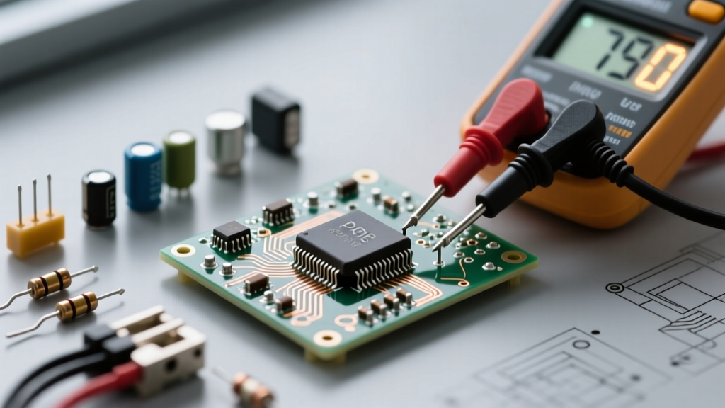
Because manufacturers like Kingbright, Lite-On, and Wurth Elektronik occasionally deviate from the standard 'longest pin is common' rule, relying on visual inspection alone is a recipe for failure. When dealing with salvaged or unmarked rgb led pins, your digital multimeter (DMM) is your most reliable diagnostic tool.
Pro-Tip: Set your multimeter to 'Diode Test' mode. This mode outputs a small test voltage (usually 2V to 3V) and measures the forward voltage drop.
Diagnostic Framework:
- Place the black (negative) probe on the suspected common pin (usually pin 2).
- Touch the red (positive) probe to pins 1, 3, and 4.
- If the LED lights up faintly on all three outer pins, you have identified a Common Cathode LED, and the DMM is displaying the Vf of each die.
- If nothing happens, reverse the probes: place the red probe on pin 2 and the black probe on the outer pins. If they illuminate, it is a Common Anode LED.
- Note on Blue/Green Dies: Standard DMMs output ~2.5V in diode mode. Because Blue and Green dies require ~3.2V to conduct, they may not illuminate during testing. Look for the voltage drop reading on the DMM screen instead; a reading of 'OL' (Open Loop) vs '2.8V' will confirm the pin connection even if the die remains dark.
Microcontroller Wiring Frameworks
Choosing between analog rgb led pins and addressable data pins ultimately depends on your microcontroller's architecture and your project's complexity.
- For Simple Status Indicators (Arduino Nano / ATmega328P): Use Common Cathode through-hole LEDs. The ATmega architecture handles current sinking and sourcing equally well (up to 20mA per pin), and the
analogWrite()function maps perfectly to Active HIGH logic. - For High-Density Lighting (ESP32 / Teensy 4.0): Use WS2812B or SK6812 addressable LEDs. The ESP32's 3.3V logic outputs can sometimes fail to trigger the 5V WS2812B DIN pin reliably. In this scenario, you must use a level shifter (like the 74AHCT125) between the ESP32 GPIO and the LED data pin, or opt for the SK6812 3.3V compatible variants.
- For Battery-Powered Wearables: Avoid Common Anode LEDs if your microcontroller operates in a sleep state where GPIO pins default to HIGH-impedance or HIGH states, as this can cause phantom current leakage through the dies. Addressable LEDs with a dedicated power MOSFET are the superior alternative for strict power budgets.
By understanding the exact electrical topology, forward voltage requirements, and logic states of your chosen components, you can eliminate wiring errors and achieve precise color control in your next electronics build. For deeper semiconductor theory, the All About Circuits Semiconductor Textbook provides excellent foundational knowledge on how these multi-junction dies operate at the atomic level.