
The Engineering Reality: Why Calculated Values Rarely Exist
When you simulate a circuit in SPICE, the software happily accepts a resistance value of 314.15 ohms. However, when you move to the workbench to build the physical prototype, you hit a hard manufacturing wall: that exact component does not exist. This is where the standard-value resistor becomes a critical concept in practical electronics design. Manufacturing resistors to arbitrary values is economically unviable, so the electronics industry relies on standardized geometric progressions. Understanding how to navigate these series, manage rounding errors, and account for tolerance stacking is what separates theoretical hobbyists from reliable circuit designers.
Decoding the EIA Standard-Value Resistor Series
The International Electrotechnical Commission (IEC) defines the preferred numbers for resistors in the IEC 60063 standard. These are known as the E-series, and they are logarithmically spaced so that the tolerance bands of adjacent values slightly overlap, ensuring no gaps in available resistance ranges.
E12 vs. E24: The Prototyper's Dilemma
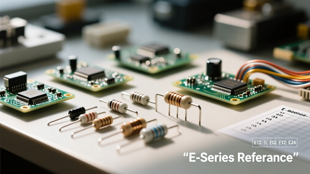
The E12 series contains 12 values per decade (e.g., 10, 12, 15, 18, 22, 27, 33, 39, 47, 56, 68, 82) and was historically tied to 10% tolerance carbon composition resistors. Today, the E24 series is the undisputed king of the prototyping bench. It includes 24 values per decade and is standard for 5% tolerance thick-film and metal-film resistors. When you buy a generic resistor assortment kit, you are almost exclusively getting E24 values. According to SparkFun's comprehensive resistor guide, sticking to E24 values ensures you can always find a replacement from local suppliers or your own bins without redesigning your PCB.
When to Upgrade to E96 and E192
For precision analog circuits, data acquisition systems, or active filter networks, the 5% tolerance and coarse steps of the E24 series introduce unacceptable errors. The E96 series (1% tolerance) provides 96 values per decade, while the E192 series (0.1% to 0.5% tolerance) offers 192 values. Using an E96 standard-value resistor allows you to get within a fraction of a percent of your theoretical SPICE calculations, which is vital for setting precise gains in operational amplifier feedback loops.
Practical Tutorial 1: LED Current Limiting with Standard Values
Let's apply this to a ubiquitous circuit application: driving a standard red LED from a 5V microcontroller GPIO pin.
- Source Voltage (Vs): 5.0V
- LED Forward Voltage (Vf): 2.1V
- Target Current (I): 20mA (0.020A)
Using Ohm's Law, the ideal resistance is R = (Vs - Vf) / I = (5.0 - 2.1) / 0.020 = 145 ohms.
You cannot buy a 145-ohm resistor. Looking at the E24 chart, the closest standard-value resistor options are 130 ohms and 150 ohms.
Which do you choose? As a rule in circuit design, when limiting current to protect a semiconductor junction, always round up to the next highest standard value. Selecting 150 ohms yields a real-world current of 19.3mA. This is visually indistinguishable from 20mA in terms of LED brightness, but it keeps the component safely within its absolute maximum ratings and reduces thermal stress on the microcontroller's internal current sink.
The Hidden Cost of Rounding: Voltage Divider Drift
While rounding up an LED resistor is harmless, rounding in a voltage divider can ruin an analog sensor reading. Suppose you need a precise 3.3V reference from a 5.0V rail to feed an ADC. The ideal ratio requires R1 = 1700 ohms and R2 = 3300 ohms. Let's look at what happens when we force standard-value resistors into this topology.
| Resistor Role | Ideal Value | Closest E24 Standard | Resulting Vout | Error from 3.3V |
|---|---|---|---|---|
| R1 (Top) | 1700 Ω | 1800 Ω | 3.235 V | -1.96% |
| R2 (Bottom) | 3300 Ω | 3300 Ω | 3.235 V | -1.96% |
| R1 (Alt E96) | 1740 Ω (1%) | 1740 Ω | 3.296 V | -0.12% |
As demonstrated in the table, using standard E24 values introduces a nearly 2% error. If your ADC has a 10-bit resolution (1024 steps), a 2% error translates to a 20-step offset before you even read the sensor data. In precision applications, you must either use E96 1% resistors or implement a trimpot for manual calibration. All About Circuits provides extensive lookup tables for these exact scenarios, proving that standard value selection is a foundational engineering skill, not just a purchasing detail.
Advanced Application: Managing Thermal Noise and Tolerance Stacking
When selecting a standard-value resistor for high-impedance nodes, you must consider Johnson-Nyquist thermal noise. The noise voltage is proportional to the square root of the resistance ($V_n = \sqrt{4k_B T R \Delta f}$). If you design a voltage divider using 1MΩ and 2.2MΩ standard values to minimize power consumption, you are injecting significant thermal noise into your signal path. In low-noise audio or precision DC measurement circuits, it is often better to select lower standard values (e.g., 10kΩ and 22kΩ) and accept the higher quiescent current draw to maintain a high signal-to-noise ratio.
Furthermore, consider tolerance stacking. If you use two E24 5% resistors in a divider, the worst-case ratio error isn't just 5%; it can approach 10% if one resistor drifts to the extreme positive end of its tolerance band while the other drifts to the extreme negative end. For critical timing circuits (like 555 timers or RC oscillators), always pair a 5% standard-value resistor with a 1% or 2% capacitor, or upgrade both to 1% E96 components to prevent frequency drift.
Sourcing and Substitution Framework for Prototyping
When your BOM (Bill of Materials) calls for a specific standard-value resistor that is out of stock, use this substitution framework:
- Current Limiting / Pull-ups: Substitute freely within the same decade. A 4.7kΩ pull-up can easily be replaced by a 5.1kΩ or 3.9kΩ standard-value resistor without affecting logic levels.
- Power Dissipation: Never substitute a lower wattage rating. If the design calls for a 1/2W 100Ω resistor, do not use a 1/4W version, even if the resistance value is correct. Derate power by 50% for long-term reliability in enclosed cases.
- Series/Parallel Combinations: If you absolutely need a non-standard value (e.g., 315 ohms) and only have E12 values, wire a 270Ω and a 47Ω standard-value resistor in series. Be aware that this adds parasitic inductance and takes up extra PCB real estate.
Expert Prototyping Tip: Keep a 'decade box' or a dedicated drawer for E24 1% metal-film resistors in the 1kΩ to 10kΩ range. This specific range covers 80% of all op-amp feedback networks, transistor biasing networks, and filter cut-off frequency requirements, allowing you to iterate on analog designs without waiting for shipping.
Mastering the selection of the standard-value resistor bridges the gap between theoretical simulation and robust, manufacturable hardware. By respecting the E-series limitations, calculating the real-world impact of rounding, and anticipating tolerance drift, you ensure your circuits perform reliably long after the prototype leaves the bench.