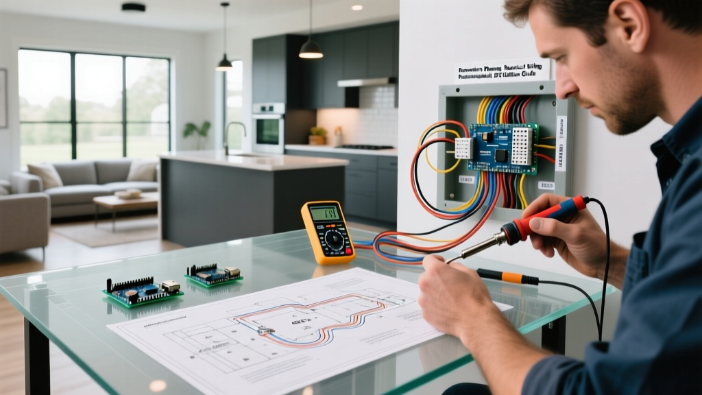

Why Potentiometers Matter in Modern Home Renovations
When planning a high-end residential renovation or a custom commercial build, standard smart switches and binary relays do not always suffice. High-end audio rooms, specialized workshop ventilation, and custom motorized blinds often require precise analog variable resistance. This is where understanding a proper wiring potentiometer diagram becomes critical for the electrical contractor or advanced DIYer. Unlike standard dimmers that use TRIAC phase-cutting, a potentiometer provides a true variable voltage or resistance signal, essential for 0-10V HVAC controllers, ERV/HRV fan speed overrides, and impedance-matching whole-home audio systems.
In this renovation planning guide, we will break down the exact terminal configurations, taper selections, and failure modes associated with integrating variable resistors into your low-voltage and signal-level wiring infrastructure.
Anatomy of a Potentiometer: Lugs, Wipers, and Tapers
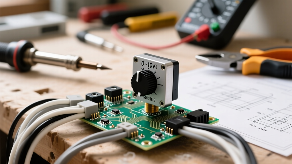
Before pulling wire through your newly framed walls, you must understand the physical and electrical anatomy of the component. A standard rotary or slide potentiometer features three terminals:
- Terminal 1 (CCW): The counter-clockwise or 'low' reference point, usually tied to ground or the negative signal return.
- Terminal 2 (Wiper): The variable output. As the shaft turns, the wiper slides across the resistive element, picking off a variable voltage or resistance.
- Terminal 3 (CW): The clockwise or 'high' reference point, typically tied to the positive voltage source or signal input.
For renovation applications, selecting the correct taper is just as important as the wiring. According to the Bourns 3852 Series Datasheet, a linear taper (B-taper) changes resistance at a constant rate, making it mandatory for 0-10V DC control signals. Conversely, an audio taper (A-taper) follows a logarithmic curve, matching the non-linear sensitivity of human hearing, and is strictly used for passive volume controls.
The Standard 3-Terminal Wiring Potentiometer Diagram
The most common configuration used in renovation signal wiring is the voltage divider setup. If you are wiring a custom 0-10V manual override for a commercial-grade VFD (Variable Frequency Drive) or an advanced ERV system, follow this mental diagram:
- Connect your 10V DC reference wire from the controller to Terminal 3 (CW).
- Connect the common ground wire to Terminal 1 (CCW).
- Connect the signal return wire (the input back to the controller) to Terminal 2 (Wiper).
As the knob rotates, the wiper divides the 10V reference down to a variable signal between 0V and 10V. Using 18 AWG or 20 AWG stranded, shielded cable (like Belden 8760) is highly recommended to prevent EMI interference from nearby 120V/240V AC lines running through the same stud bays.
Application 1: 0-10V HVAC and Fan Speed Control
In modern green-home renovations, Energy Recovery Ventilators (ERVs) are often wired with 0-10V inputs to allow for proportional boost modes (e.g., ramping up ventilation when a bathroom humidity sensor triggers). While the smart home hub handles the automated logic, building codes and best practices dictate that a manual analog override must be accessible.
When wiring a 10kΩ linear potentiometer for an HVAC control board, ensure the potentiometer is rated for at least 1/2 watt. While the current draw of a 0-10V signal is minimal (usually under 20mA), a higher wattage rating provides a thermal buffer against voltage spikes from the HVAC control board's internal switching power supply. Always route these low-voltage signal wires in separate knockouts and maintain a minimum 2-inch separation from high-voltage AC wiring to comply with NEC Article 725 regarding Class 2 and Class 3 remote-control and signaling circuits.
Application 2: Custom Whole-Home Audio Volume Controls
For audiophile renovations involving passive in-wall volume controls, the wiring potentiometer diagram shifts from a voltage divider to an impedance-matching rheostat or L-pad network. Standard potentiometers will cause amplifier instability if the impedance drops too low when multiple speaker zones are active.
Specialized impedance-matching volume controls (like those from Sonance or Xantech) utilize internal auto-former networks or specialized resistor arrays. When wiring these, you are essentially placing the device in series with the speaker line. Use 14 AWG or 12 AWG oxygen-free copper (OFC) speaker wire. The input from the amplifier connects to the 'In' terminals, and the output to the in-wall or in-ceiling speakers connects to the 'Out' terminals. Never use standard 1/4W electronic potentiometers for speaker-level signals; the amplifier's output wattage will instantly vaporize the carbon track.
Common Renovation Wiring Mistakes and Failure Modes
Even seasoned electricians can make critical errors when transitioning from high-voltage rough-ins to low-voltage analog controls. Avoid these common job-site failures:
- Wiper Bounce and Noise: If using a standard carbon-track potentiometer for a DC motor speed control, the wiper can momentarily lose contact during vibration, causing a voltage spike that resets microcontrollers. Use wirewound or conductive plastic potentiometers for high-reliability environments.
- Thermal Overload (The Rheostat Mistake): Attempting to wire a potentiometer in series with a 12V 5A LED strip to act as a manual dimmer. The 60W load will instantly burn out a standard potentiometer. As explained in All About Circuits, potentiometers are for signal control, not power dissipation. Use a PWM (Pulse Width Modulation) controller instead for high-current loads.
- Reverse Taper Wiring: Swapping Terminal 1 and Terminal 3. While electrically functional, this results in a user interface where turning the knob clockwise lowers the volume or fan speed, leading to client frustration and costly callback visits.
Pro Tip: Always label your low-voltage signal wires at both the control board and the wall box using a thermal transfer printer. A 10V signal wire looks identical to a 24V thermostat wire once the drywall is up, and miswiring them during the trim-out phase will fry the potentiometer and potentially the controller board.
Tooling and Material Checklist for the Job Site
Ensure your low-voltage trim-out kit includes the following specialized items for potentiometer integration:
| Item | Specification | Renovation Use Case |
|---|---|---|
| Shielded Twisted Pair Cable | 20 AWG, 2-Conductor (e.g., Belden 8760) | 0-10V HVAC and ERV signal runs to prevent EMI. |
| Wirewound Potentiometer | 10kΩ, Linear, 2W (e.g., Bourns 53 Series) | Heavy-duty manual overrides for workshop VFDs. |
| Low-Voltage Mud Rings | 1-Gang, Deep Profile | Provides extra depth for the bulky terminals and wire loops behind the knob. |
| Conductive Plastic Pot | 10kΩ, Audio Taper, 1/2W | High-end passive audio zone controls requiring smooth tracking. |
| Dielectric Grease | Non-conductive silicone paste | Applied to the shaft bushing to prevent drywall dust ingress during sanding. |
Integrating Analog Controls with Smart Home Ecosystems
A major trend in 2026 renovation planning is the hybrid approach: combining the tactile satisfaction of analog knobs with smart home telemetry. By wiring a potentiometer to a low-voltage analog-to-digital converter (ADC) module (such as those found in ESP32-based custom sensors or commercial Shelly Plus I4 DC inputs), you can map the physical rotation of a knob to trigger digital scenes.
For example, a beautifully machined aluminum knob in the kitchen can serve as a manual dimmer for under-cabinet lighting. The potentiometer acts as a voltage divider feeding 0-3.3V into an ADC. The microcontroller reads the voltage, translates it to a percentage, and sends a Zigbee or Matter command to the smart LED drivers. This requires wiring the potentiometer strictly as a voltage divider to the microcontroller's GPIO pins, completely isolating the high-power LED drivers from the analog control circuit. For deeper insights into analog control signaling, refer to EC&M's guide on 0-10V control systems.
Final Commissioning and Testing
Before closing up the wall or installing the final faceplate, always commission the potentiometer circuit with a digital multimeter. Set your meter to DC Volts, place the probes on the Wiper (Terminal 2) and Ground (Terminal 1), and rotate the shaft through its full mechanical travel. The voltage should sweep smoothly from 0V to your reference voltage (e.g., 10V) without any sudden drops or 'dead spots' which indicate a damaged carbon track or contaminated wiper. By treating your wiring potentiometer diagram with the same rigor as your high-voltage service panel, you ensure a flawless, high-performance finish for your renovation clients.