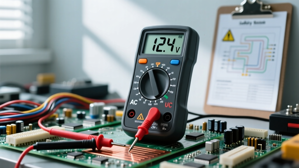

Measuring voltage is the most fundamental skill in electrical diagnostics and electronics prototyping. Whether you are troubleshooting a dead wall outlet, testing a DIY Arduino power supply, or checking if a 9V battery is truly dead, knowing how to read volts with a multimeter is your first line of defense against component failure and electrical hazards. In this comprehensive beginner tutorial, we will break down the exact steps, safety protocols, and display readings you need to master voltage measurement.
The Physics of the Dial: AC vs. DC Voltage
Before touching the probes, you must understand the two distinct types of voltage your multimeter can measure. Voltage is the electrical potential difference between two points, but it flows in different ways depending on the source.
- Direct Current (DC): Represented on your multimeter dial by a V with a solid line and a dashed line beneath it (V⎓). DC voltage flows in a single, constant direction. Common sources include batteries, solar panels, and USB power supplies.
- Alternating Current (AC): Represented by a V with a wavy line next to it (V~). AC voltage periodically reverses direction. Common sources include household wall outlets, generators, and the mains power grid.
Setting your dial to the wrong mode will result in inaccurate readings or a display reading of zero. Always match the dial symbol to the circuit you are testing.
Multimeter Anatomy and Safety Categories (CAT Ratings)
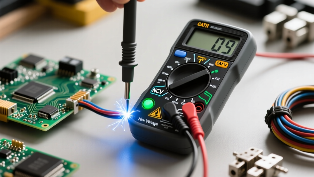
When learning how to read volts with a multimeter, safety is paramount. Not all multimeters are built to handle high-energy household circuits. According to Fluke Corporation's Guide to CAT Ratings, multimeters are classified by Measurement Categories (CAT) to protect users from transient voltage spikes.
Understanding CAT Ratings for Beginners
- CAT I: Protected electronics, signal levels, and low-energy circuits.
- CAT II: Single-phase receptacle outlets (e.g., plugging in a lamp or a DIY appliance). Minimum requirement for household DIY.
- CAT III: Three-phase distribution, single-phase commercial lighting, and fixed motor loads. Required for testing hardwired appliances and breaker panels.
- CAT IV: Three-phase utility connections, outdoor service entrances, and primary metering.
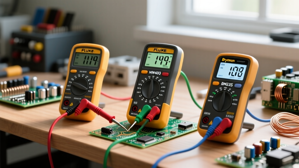
Pro Tip: If you are buying your first multimeter for home DIY and basic electronics, look for a minimum rating of CAT II 600V or CAT III 300V. Budget models like the Klein Tools MM400 (approx. $45) offer CAT III 600V protection, making them excellent entry-level choices.
Step-by-Step: How to Read Volts with a Multimeter (DC Circuits)
Let us start with the safest and most common beginner task: testing a DC power source. We will use a standard alkaline AA battery as our test subject.
Step 1: Probe Placement
Insert the black probe into the port labeled COM (Common/Ground). Insert the red probe into the port labeled VΩmA or simply V. Never insert the red probe into the '10A' or 'A' port when measuring voltage, as this creates a dead short and will blow the multimeter's internal fuse.
Step 2: Dial Selection
Turn the dial to the DC Voltage setting (V⎓). If your multimeter is manual-ranging, select a range higher than your expected voltage. For a 1.5V AA battery, select the 20V setting. If you have an auto-ranging multimeter (like the Fluke 117), simply select DC Volts and let the meter do the work.
Step 3: Taking the Measurement
Touch the red probe to the positive terminal (the raised bump) of the battery, and the black probe to the negative terminal (the flat side). Read the display.
- Fresh AA Battery: 1.55V to 1.60V
- Used but Usable: 1.30V to 1.45V
- Dead/Depleted: Below 1.20V
Step-by-Step: Measuring AC Voltage (Household Circuits)
Measuring AC voltage requires stricter safety discipline due to the higher energy potential. We will test a standard North American NEMA 1-15R 120V wall outlet.
- Inspect Probes: Ensure probe insulation is intact with no exposed copper wire. Wear safety glasses.
- Set the Dial: Turn the dial to AC Voltage (V~). Ensure it is rated for at least 200V or 600V on a manual-ranging meter.
- Insert Probes: Hold the probes by the insulated grips. Insert the red probe into the shorter (Hot) slot, and the black probe into the longer (Neutral) slot.
- Read the Display: A healthy US residential circuit should read between 110V and 125V. If it reads significantly lower (e.g., 95V), you may have a loose neutral connection or an overloaded circuit.
For deeper insights into testing household circuits safely, refer to the comprehensive SparkFun Multimeter Tutorial, which covers probe isolation techniques.
Manual Ranging vs. Auto-Ranging: Which is Better?
When figuring out how to read volts with a multimeter, you will encounter two distinct architectures. Understanding the difference saves time and prevents misinterpretation of data.
| Feature | Manual-Ranging Multimeter | Auto-Ranging Multimeter |
|---|---|---|
| Cost | $10 - $40 | $40 - $250+ |
| Speed | Instant (if range is pre-selected) | 1-2 seconds to lock onto range |
| Beginner Friendliness | Low (requires estimating voltage) | High (just select AC or DC) |
| Best Use Case | Known circuits, basic battery testing | Unknown circuits, troubleshooting |
As noted by Electronics Notes, auto-ranging meters are vastly superior for beginners because they eliminate the risk of selecting a range that is too low, which triggers an overload error.
Decoding Display Readings and Common Errors
Beginners often panic when the multimeter display shows something other than a clean number. Here is a troubleshooting matrix for common voltage reading anomalies.
| Display Reading | Meaning | Action Required |
|---|---|---|
| OL or 1 (left side) | Overload / Out of Range | Increase the voltage range setting on the dial (e.g., switch from 2V to 20V). |
| -12.4V (Negative) | Reversed Polarity | Swap the red and black probes. The meter is safe; the red probe is touching the ground/negative side. |
| 0.00V | No Potential Difference | Check if the circuit is powered on. Test probe continuity by touching the tips together. |
| Fluctuating Digits | AC Noise / Ghost Voltage | Enable 'LoZ' (Low Impedance) mode if available, or verify probe contact is clean and tight. |
The 'Ghost Voltage' Phenomenon
If you are testing a multi-conductor cable and read 40V on a disconnected wire, you are likely seeing 'ghost voltage.' This is caused by capacitive coupling from adjacent live wires. High-impedance digital multimeters are so sensitive they pick up this stray energy. Professional meters like the Fluke 117 feature a 'LoZ' (Low Impedance) mode that safely bleeds off this ghost voltage, dropping the reading to a true 0V.
Critical Maintenance for Accurate Readings
Your multimeter is only as accurate as its internal power supply. If you see a faint battery icon on the LCD screen, replace the 9V or AAA batteries immediately. A low multimeter battery causes the internal Analog-to-Digital Converter (ADC) to miscalculate, resulting in 'drifting' numbers that can trick you into thinking a power supply is failing when it is actually your test equipment that is dying.
Furthermore, always store your multimeter with the dial set to the 'OFF' position or the highest AC Voltage setting. Leaving the dial on continuity or resistance mode while accidentally probing a live circuit will instantly destroy the internal shunt resistors and ruin the meter.