
Beyond the PDF: Navigating the RP2040 Ecosystem
When engineers and makers first open the Raspberry Pi Pico Datasheet, they are often confronted with a dense, 600+ page technical manual that covers everything from silicon die layouts to USB mass-storage bootroms. However, reading the datasheet in a vacuum is a common pitfall. The true power of the Pico lies in understanding how its silicon specifications map to the broader Raspberry Pi microcontroller ecosystem, including the C/C++ SDK, MicroPython runtime, and third-party hardware integrations.
This ecosystem overview decodes the critical hardware specifications, pinout constraints, and peripheral behaviors documented in the datasheet, translating raw silicon data into actionable insights for real-world PCB design and firmware architecture.
Core Silicon: Dissecting the RP2040 Microcontroller
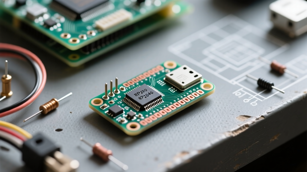
At the heart of the Pico is the RP2040, a dual-core ARM Cortex-M0+ processor. While the datasheet lists a default clock speed of 133 MHz, the ecosystem reality is far more flexible. The PLL (Phase-Locked Loop) configuration allows developers to overclock the silicon to 250 MHz or even 300 MHz with adequate cooling and voltage regulation. However, the datasheet warns of a critical bottleneck: the XIP (Execute In Place) interface.
Memory Architecture and XIP Execution
The RP2040 features 264 KB of on-chip SRAM, divided into four striped banks to minimize bus contention between the two cores and the DMA controller. Because there is no internal flash memory, the Pico relies on a 2 MB external QSPI flash chip (W25Q16JV). Code is executed directly from this flash via the XIP cache.
- XIP Cache Size: 16 KB direct-mapped cache.
- Performance Bottleneck: If your code exceeds the 16 KB cache or suffers from poor spatial locality, the CPU stalls while fetching from the QSPI flash, effectively negating the benefits of a 250 MHz overclock.
- Ecosystem Tip: Use the
__not_in_flash_func()macro in the Pico C/C++ SDK to force time-critical interrupt service routines (ISRs) into SRAM, bypassing XIP latency entirely.
The Pinout Matrix: GPIO Capabilities and Constraints
The Pico exposes 26 multi-function GPIO pins out of the RP2040's 30 available pins. A careful reading of the Hardware Design with RP2040 guide reveals strict limitations that frequently trap beginners, particularly regarding 5V tolerance and ADC noise.
| Peripheral Block | Available Instances | Pico Pin Mapping | Datasheet Constraints & Ecosystem Notes |
|---|---|---|---|
| UART | 2 Blocks (8 Pin Options) | GP0/1, GP4/5, GP8/9, GP12/13, etc. | Hardware flow control (RTS/CTS) consumes adjacent pins. No native RS-485 direction control. |
| I2C | 2 Blocks (8 Pin Options) | GP0/1, GP4/5, GP8/9, etc. | Internal pull-ups are weak (~50kΩ). Always add external 4.7kΩ pull-ups for reliable bus capacitance. |
| SPI | 2 Blocks (8 Pin Options) | GP16-19 (SPI0), GP8-11 (SPI1) | SPI1 is partially consumed by the Pico W's Wi-Fi module. Verify board variant before routing. |
| ADC | 1 Block (4 Channels + Temp) | GP26-28, ADC_VREF | 12-bit resolution, but effective accuracy is ~8.5 bits due to digital switching noise. Requires external LC filtering for precision. |
Expert Warning: The RP2040 GPIO pins are strictly 3.3V tolerant. Connecting a 5V I2C sensor directly to GP4/GP5 will permanently damage the silicon's ESD protection diodes, leading to phantom bus pulls and eventual core failure. Always use logic level shifters in mixed-voltage ecosystems.
Programmable I/O (PIO): The Hidden Ecosystem Engine
The most revolutionary feature detailed in the Raspberry Pi Pico datasheet is the Programmable I/O (PIO) subsystem. PIO allows developers to create custom hardware interfaces without writing complex CPU interrupt handlers. The ecosystem supports this via the pioasm assembler, which translates custom instruction sets into state machine configurations.
The RP2040 contains two PIO blocks, each with four state machines and a 32-word FIFO (First-In-First-Out) buffer. This architecture enables deterministic, cycle-accurate signal generation. Real-world ecosystem applications include:
- WS2812B LED Control: Handled entirely by PIO, freeing both Cortex-M0+ cores for complex rendering logic.
- Quadrature Encoders: Decoded in hardware via PIO, eliminating missed steps during high-RPM motor tracking.
- VGA Video Output: Generating precise H-sync and V-sync timings alongside pixel streaming directly from the DMA to the PIO FIFO.
Power Consumption Profiles and Hardware Failure Modes
Understanding the power tree documented in the datasheet is vital for battery-operated IoT deployments. The Pico utilizes an RT5000 PMIC to step down the USB VBUS (5V) or VSYS (1.8V to 5.5V) input to the 1.1V core voltage and 3.3V I/O voltage.
Sleep vs. Dormant Modes
The datasheet outlines multiple low-power states, but the software ecosystem (specifically MicroPython) struggles to expose them cleanly. In Sleep Mode, the system clock is halted, but the SRAM and core power remain active, drawing roughly 1.3 mA. In Dormant Mode, the core power is gated, and the chip waits for an external GPIO interrupt or RTC alarm, dropping consumption to under 0.5 mA. However, waking from Dormant mode requires a complete re-initialization of the PLL and XIP cache, which introduces a latency spike of several milliseconds.
The Pico W Peripheral Collision
When integrating the Pico W into your ecosystem, the datasheet reveals a hidden hardware collision. The Infineon CYW43439 Wi-Fi/Bluetooth chip communicates with the RP2040 via a dedicated SPI bus. This bus internally hijacks GPIO 23, 24, 25, and 29. While these pins are not broken out to the external headers on the Pico W, attempting to use them internally or routing traces to them on a custom RP2040 carrier board based on the standard Pico schematic will cause catastrophic bus contention and Wi-Fi drops.
Real-World Troubleshooting: When the Datasheet Meets Reality
Hardware debugging often requires looking past the idealized block diagrams in the datasheet. Here are three common failure modes and their ecosystem-level solutions:
- USB Enumeration Failures: If the Pico fails to mount as a mass storage device, the USB D+ and D- lines may be suffering from impedance mismatch or EMI. The datasheet mandates a 27Ω series resistor on the USB data lines. Omitting these on custom PCBs leads to intermittent disconnects.
- Flash Bricking via XIP Misconfiguration: Accidentally overwriting the XIP setup function in the first 256 bytes of flash can prevent the bootrom from executing your code. Recovery: Hold the BOOTSEL button while plugging in USB. This forces the RP2040 bootrom to bypass the external flash entirely and mount as a raw USB drive, allowing you to drag and drop a fresh UF2 firmware file.
- Brownout Resets: When driving high-current peripherals like relays or servo motors directly from the 3V3 OUT pin, the voltage can dip below the RT5000's undervoltage lockout threshold. This triggers a hard reset loop. Always isolate high-current loads using external MOSFETs powered directly from VSYS.
Software Ecosystem Integration
The hardware registers detailed in the datasheet are abstracted by the Pico C/C++ SDK. However, for maximum performance, developers must bridge the gap between the SDK and the silicon. The RP2040 includes dedicated hardware interpolators and an 8-cycle hardware divider—features rarely found in competing microcontrollers like the STM32 or ATmega328P. By directly manipulating the SIO (Single-Cycle I/O) registers via pointer dereferencing, developers can execute complex mathematical transformations for motor control or DSP (Digital Signal Processing) tasks in a fraction of the time required by standard software libraries.
Ultimately, the Raspberry Pi Pico datasheet is not just a specification sheet; it is a blueprint for a highly deterministic, deeply customizable hardware ecosystem. Mastering its nuances is the key to transitioning from basic Arduino-style prototyping to professional-grade embedded systems engineering.