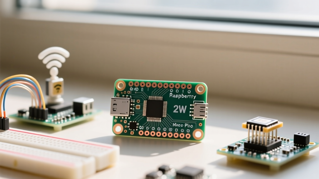

The transition from the RP2040 to the RP2350 microcontroller marks a significant evolution in the maker ecosystem. For IoT developers, the Raspberry Pi Pico 2W pinout represents both a familiar physical footprint and a vastly expanded internal peripheral map. Priced around $7, the Pico 2 W integrates the dual-core ARM Cortex-M33 (and RISC-V Hazard3) RP2350 chip alongside the Infineon CYW43439 Wi-Fi and Bluetooth LE transceiver. Whether you are migrating from the original Pico W or starting fresh, understanding the nuanced pin multiplexing and power delivery requirements is critical for a successful first wireless project.
Decoding the Raspberry Pi Pico 2W Pinout
At first glance, the Pico 2 W retains the classic 40-pin DIP module layout. It breaks out 26 multifunction GPIO pins (GP0 through GP22, and GP26 through GP28). However, the internal routing on the RP2350 differs significantly from its predecessor. The RP2350 features an expanded alternate function matrix, meaning almost any pin can be mapped to UART, I2C, or SPI via the new programmable I/O (PIO) and advanced multiplexers.
| Pin Number | GPIO | Primary IoT Function | RP2350 Specific Notes |
|---|---|---|---|
| 1, 2 | GP0, GP1 | UART0 TX/RX | Default debug console, 5V tolerant via PIO. |
| 4, 5 | GP2, GP3 | I2C1 SDA/SCL | Supports higher I2C clock stretching limits. |
| 6, 7 | GP4, GP5 | I2C0 SDA/SCL | Recommended for external sensor buses. |
| 19, 20 | GP14, GP15 | SPI1 MISO/MOSI | Useful for secondary SPI displays. |
| 31, 32 | GP26, GP27 | ADC0, ADC1 | Redesigned ADC block fixes RP2040 non-linearity. |
| 34 | GP28 | ADC2 / SPI MISO | Can be configured as a high-speed SPI input. |
| 36 | 3V3 OUT | Logic Power | Max 300mA draw when powered via USB. |
| 40 | VBUS | USB 5V Input | Directly tied to USB power rail. |
The CYW43439 Wireless Routing
A crucial aspect of the Raspberry Pi Pico 2W pinout is understanding which pins you cannot use. The CYW43439 wireless chip communicates with the RP2350 via a dedicated SPI bus and control lines. Specifically, GP23 (WL_ON), GP24 (SPI DAT1), GP25 (SPI CMD/CSn), and GP29 (SPI CLK) are permanently reserved for the wireless module and the onboard Switched-Mode Power Supply (SMPS) control. Attempting to reassign these pins in your firmware will result in immediate Wi-Fi/Bluetooth failure and potential kernel panics in the MicroPython network stack.
The ADC Overhaul
If your first project involves analog sensors, you will benefit from the RP2350's redesigned Analog-to-Digital Converter. The original RP2040 suffered from a known non-linearity issue and a high noise floor on the ADC pins. The Pico 2 W resolves this with an improved internal reference and better isolation. GP26, GP27, and GP28 now provide highly accurate 12-bit readings, making them ideal for precision analog telemetry without needing an external ADC chip.
Essential Hardware Setup for Wireless Projects
Wireless transmission requires sudden bursts of current. When the CYW43439 chip transmits a Wi-Fi packet, the Pico 2 W can experience current spikes exceeding 150mA. If you are powering the board via a low-quality USB cable or an underpowered hub, the voltage on the VBUS rail will droop, triggering the RP2350's brownout detector and causing a silent reboot.
Setup Best Practices:
- Power Source: Use a high-quality 5V/2A USB power supply and a short, thick USB-C cable.
- Decoupling: If designing a custom carrier PCB, place a 100µF low-ESR tantalum or ceramic capacitor directly across the VSYS and GND pins to buffer RF transmission spikes.
- Antenna Clearance: The Pico 2 W uses a PCB trace antenna on the top edge. Keep all ground planes, metal enclosures, and battery packs at least 10mm away from the antenna quadrant to prevent RF detuning and signal loss.
Flashing MicroPython: The Architecture Shift
The RP2350 is unique because it contains both ARM Cortex-M33 and RISC-V Hazard3 cores. When downloading MicroPython for the Pico 2 W from the MicroPython RP2 Quick Reference page, you will notice multiple UF2 files. For standard IoT projects, select the ARM build, as it currently offers the widest compatibility with pre-compiled C-modules and Wi-Fi drivers. Hold the BOOTSEL button, plug in the USB-C cable, and drag the .uf2 file onto the RPI-RP2 mass storage drive.
First Project: Wi-Fi Telemetry Node
Let us build a practical first project: a Wi-Fi connected environmental monitor. We will use the BME280 sensor via I2C to read temperature and humidity, then connect to a local network.
Wiring the BME280 Sensor (I2C)
We will utilize I2C0 on the Pico 2 W. Connect your BME280 breakout board as follows:
- VCC to 3V3 OUT (Pin 36)
- GND to GND (Pin 38)
- SDA to GP4 (Pin 6)
- SCL to GP5 (Pin 7)
Note: Ensure your BME280 breakout has onboard 4.7kΩ pull-up resistors. If it does not, the I2C bus will hang during initialization.
The MicroPython Code
Save the following script as main.py on the Pico 2 W's file system using Thonny or VS Code. This script handles the Wi-Fi handshake, initializes the I2C bus, and polls the sensor.
import network
import machine
import time
import bme280

# Network Credentials
ssid = 'YourNetworkSSID'
password = 'YourNetworkPassword'

# Initialize Wi-Fi Station Interface
wlan = network.WLAN(network.STA_IF)
wlan.active(True)
# Prevent Wi-Fi from sleeping to ensure stable telemetry
wlan.config(pm = 0xa11140)
print('Connecting to Wi-Fi...')
wlan.connect(ssid, password)

# Initialize I2C0 on GP4 (SDA) and GP5 (SCL)
i2c = machine.I2C(0, sda=machine.Pin(4), scl=machine.Pin(5), freq=400000)
bme = bme280.BME280(i2c=i2c)

# Wait for network connection with a 15-second timeout
timeout = 30
while not wlan.isconnected() and timeout > 0:
    time.sleep(0.5)
    timeout -= 1

if wlan.isconnected():
    print('Connected! IP Address:', wlan.ifconfig()[0])
else:
    print('Wi-Fi connection failed. Rebooting...')
    machine.reset()

# Main Telemetry Loop
while True:
    try:
        temp = bme.temperature
        hum = bme.humidity
        pres = bme.pressure
        print(f'Temp: {temp} | Humidity: {hum} | Pressure: {pres}')
    except OSError as e:
        print('I2C Communication Error:', e)

    # Deep sleep or delay for 10 seconds
    time.sleep(10)
Troubleshooting Common Pico 2W Failures
Even with a perfect understanding of the Raspberry Pi Pico 2W pinout, hardware and RF quirks can derail your first project. Consult the Raspberry Pi Pico Documentation for deeper schematic analysis if you encounter these specific failure modes:
- The 'Guru Meditation' Wi-Fi Reset: If your board resets exactly when
wlan.connect()is called, you are experiencing a brownout. The RF power amplifier is drawing more current than your USB port can supply. Switch to a powered USB hub or add bulk capacitance to the 5V rail. - I2C Bus Lockups: The RP2350 I2C peripheral is highly sensitive to missing pull-up resistors. If the code hangs at
bme280.BME280(i2c=i2c), measure the voltage on GP4 and GP5 with a multimeter. If they are not sitting at ~3.3V, add external 4.7kΩ pull-up resistors to the 3V3 rail. - Thermal Throttling on ADC: If your analog readings drift over time, remember that the RP2350 generates more heat than the RP2040 due to the higher clock speeds and wireless baseband processing. Keep heat-generating components (like linear voltage regulators) away from the ADC pins (GP26-GP28) to prevent thermal noise injection.
Expert PCB Layout Tip: When designing a custom board for the Pico 2 W, do not route any high-speed digital traces directly under the CYW43439 module or its antenna quadrant. The RP2350's new HSTX (High-Speed Transmit) peripheral can output DVI signals directly, but these high-frequency harmonics can easily desensitize the 2.4GHz Wi-Fi receiver if proper ground shielding is not maintained between the layers.
By mastering the physical and logical constraints of the Raspberry Pi Pico 2W pinout, you unlock the full potential of the RP2350 architecture. Whether you are deploying a fleet of RISC-V based sensor nodes or building a secure ARM-based IoT gateway, proper power management and peripheral routing are the foundations of a reliable wireless device.