
Why the Arduino Nano Remains the Ultimate Prototyping Bridge
When transitioning from breadboard experiments to permanent, embedded installations, the standard Arduino Uno is simply too bulky. Enter the Arduino Nano. Measuring just 18mm x 45mm, it offers nearly identical I/O capabilities to the Uno but in a form factor that solders directly into custom PCBs or fits into tight project enclosures. In 2026, despite the influx of ESP32 and RP2040 boards, the Nano architecture remains the gold standard for low-power, 5V logic microcontroller projects where Wi-Fi is unnecessary and simplicity is paramount.
This comprehensive setup guide will walk you through the hardware variations, the notorious driver hurdles associated with clone boards, and a complete first project to verify your toolchain.
Choosing Your Hardware: Official vs. Clone Nano Boards
Before opening the Arduino IDE, you must understand exactly which silicon you are working with. The market is currently split between official Arduino releases and third-party clones. Here is how they compare for modern makers:
| Board Variant | Microcontroller | Logic Level | Avg. Price (2026) | Best Use Case |
|---|---|---|---|---|
| Classic Nano (Clone) | ATmega328P | 5V | $3.50 - $5.00 | Budget learning, high-volume simple I/O |
| Official Nano Every | ATmega4809 | 5V | $12.50 - $14.00 | Complex timing, more SRAM, official support |
| Official Nano 33 IoT | SAMD21 + NINA-W10 | 3.3V | $20.00 - $23.00 | Wi-Fi/Bluetooth required, low-power sensors |
For this tutorial, we are focusing on the classic ATmega328P architecture (both official and clone), as it represents 85% of beginner setups.
The CH340 Driver Hurdle (And How to Clear It)
If you purchased a clone Nano from AliExpress, Amazon, or a local maker shop, it likely uses the CH340G or CH341A USB-to-Serial chip instead of the official FTDI or ATmega16U2 chips. Modern operating systems (Windows 11 and macOS Sonoma/Sequoia) sometimes fail to automatically fetch the correct CH340 drivers, resulting in the board not appearing in your COM port list.
Step-by-Step Driver Installation
- Download the IDE: Ensure you have the latest Arduino IDE 2.3.x from the official Arduino software page.
- Identify the Chip: Look at the surface-mount chip near the USB port. If it says 'CH340', you need the specific driver.
- Windows 11 Users: Download the CH341SER.EXE from the manufacturer (WCH). Run the installer and click 'INSTALL'. You must restart the Arduino IDE after installation.
- macOS Users: Apple Silicon (M1/M2/M3) Macs require the specific ARM64 version of the CH340 driver. After installing, you may need to approve the kernel extension in System Settings > Privacy & Security.
Expert Tip: If your board uses the CP2102 chip instead of the CH340, the Silicon Labs CP210x VCP drivers are required. Always visually verify the USB bridge chip before downloading random driver executables.
First Project Setup: Precision PWM LED Fader
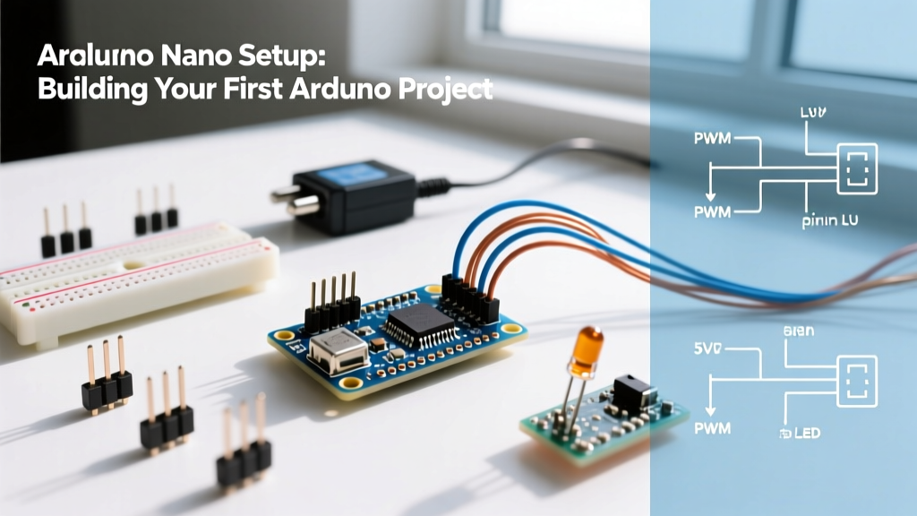
To verify your toolchain, wiring, and code upload pipeline, we will build an interactive PWM (Pulse Width Modulation) fader. This project reads an analog voltage from a potentiometer and maps it to a PWM signal to smoothly fade an LED, while simultaneously plotting the data in the IDE.
Component BOM & Wiring Matrix
Pay close attention to the pin assignments. The Nano operates at 5V, meaning we must use a current-limiting resistor for standard 5mm LEDs to prevent burning out the microcontroller's GPIO pin.
| Component | Nano Pin | Wire Color | Technical Notes |
|---|---|---|---|
| 10kΩ Potentiometer (Wiper) | A0 | Yellow | Analog Input (10-bit resolution) |
| Potentiometer (Leg 1) | 5V | Red | Provides reference voltage |
| Potentiometer (Leg 3) | GND | Black | Completes the voltage divider |
| 220Ω Resistor | D9 (PWM) | Orange | Limits current to ~13mA @ 2Vf LED |
| 5mm Red LED (Anode) | Resistor | - | Long leg connects to resistor |
| 5mm Red LED (Cathode) | GND | Black | Short leg to ground rail |
Unlike the Arduino Uno, the classic ATmega328P Nano breaks out pins A6 and A7. Beginners often attempt to use these as digital outputs or PWM pins. This will fail. On the Nano's specific package, A6 and A7 are strictly hardwired to the internal ADC (Analog-to-Digital Converter). They cannot be driven HIGH or LOW. Always use A0-A5 for analog, and D3, D5, D6, D9, D10, D11 for PWM.
The C++ Sketch
Upload the following code. Note the use of the F() macro for serial strings, which stores them in Flash memory rather than consuming the Nano's limited 2KB SRAM.
// Arduino Nano Precision PWM Fader
// Target: ATmega328P (5V Logic)

const int potPin = A0;    // Potentiometer wiper
const int ledPin = 9;     // D9 is a hardware PWM pin

int sensorValue = 0;
int pwmOutput = 0;

void setup() {
  pinMode(ledPin, OUTPUT);
  Serial.begin(115200);   // High baud rate for smooth plotting

  // Startup pulse to confirm hardware is alive
  for(int i=0; i<3; i++) {
    digitalWrite(ledPin, HIGH);
    delay(100);
    digitalWrite(ledPin, LOW);
    delay(100);
  }
}

void loop() {
  sensorValue = analogRead(potPin); // Reads 0-1023

  // Map 10-bit analog to 8-bit PWM (0-255)
  pwmOutput = map(sensorValue, 0, 1023, 0, 255);

  analogWrite(ledPin, pwmOutput);

  // Serial output formatted for Arduino Serial Plotter
  Serial.print(F("Sensor:"));
  Serial.print(sensorValue);
  Serial.print(F(",PWM:"));
  Serial.println(pwmOutput);

  delay(20); // 50Hz update rate for smooth visual fading
}
Troubleshooting Common Nano Upload Failures
If you hit the 'Upload' button and are met with a wall of orange text, do not panic. 90% of Nano setup issues fall into three specific categories. For deeper hardware documentation, refer to the official Arduino hardware docs or the SparkFun Arduino Guide.
1. The 'Old Bootloader' Error
Symptom: avrdude: stk500_recv(): programmer is not responding
Cause: Most clone Nanos ship with an older version of the Optiboot bootloader to save flash space.
Fix: In the Arduino IDE, go to Tools > Processor and change the selection from 'ATmega328P' to 'ATmega328P (Old Bootloader)'. This adjusts the upload baud rate from 115200 to 57600, matching the clone's silicon.
2. The Phantom COM Port
Symptom: The IDE shows a COM port, but upload fails instantly.
Cause: You are selecting a Bluetooth virtual COM port or a 3D printer port instead of the Nano.
Fix: Unplug the Nano. Check the Tools > Port list and note which ports disappear. Plug it back in, wait 3 seconds for the OS to enumerate the USB device, and select the newly appeared port.
3. USB Cable Charge-Only Trap
Symptom: The Nano powers on (LED lights up), but it never appears in Device Manager or the IDE Port list.
Cause: You are using a Micro-USB cable that lacks the internal D+ and D- data wires (common with cheap phone chargers).
Fix: Swap to a verified data-sync Micro-USB cable. If you have a multimeter, verify continuity on the two inner pins of the USB-A to Micro-B cable.
Next Steps for Your Nano Journey
Once your PWM fader is running smoothly and the Serial Plotter shows a clean, mapped curve, your toolchain is fully verified. You are now ready to integrate I2C sensors (like the BME280 or OLED displays), utilize hardware interrupts on D2 and D3, or design a custom breakout board in KiCad using the Nano as a through-hole daughterboard. The Arduino Nano remains an indispensable workhorse in the embedded DIY space, provided you respect its specific pinout quirks and bootloader variations.