
Deconstructing the Schematic Symbol for a Potentiometer
When designing, analyzing, or troubleshooting electronic schematics, correctly interpreting the symbol for a potentiometer is a foundational skill. A potentiometer (often called a 'pot') is a three-terminal variable resistor used to control voltage or current. However, because it can be wired in multiple configurations, its schematic representation can vary depending on the engineer's intent and the regional drafting standards (ANSI/IEEE vs. IEC).
At its core, the standard symbol for a potentiometer consists of two distinct elements:
- The Resistive Element: Represented by either a zig-zag line (ANSI/IEEE standard common in North America) or an empty rectangle (IEC standard common in Europe and international datasheets). This represents the fixed carbon, cermet, or wirewound resistive track.
- The Wiper (Arrow): An arrow pointing toward or intersecting the resistive element. This arrow represents the movable contact (the wiper) that slides along the track to divide the resistance.
Expert Insight: Never confuse the arrow on a potentiometer symbol with the arrow on a variable capacitor or variable inductor. In a potentiometer, the arrow specifically denotes a physical, mechanical wiper making electrical contact with a resistive strip.
Mapping the Three Terminals
The standard schematic symbol explicitly shows three connection points. Understanding these is critical for translating a 2D drawing into a 3D breadboard or PCB layout:
- Terminal 1 (CCW / Ground): One end of the resistive track. Usually connected to the ground or lower voltage potential.
- Terminal 2 (The Wiper): The point where the arrow connects to the resistor. This is your output (
V_out) in a voltage divider setup. Physically, this is almost always the center pin on standard through-hole potentiometers like the Bourns 3296 series. - Terminal 3 (CW / VCC): The opposite end of the resistive track. Usually connected to the positive supply voltage.
Crucial Variations in Potentiometer Symbols
While the three-terminal voltage divider is the most common configuration, circuit application tutorials must account for variations. The symbol for a potentiometer changes subtly based on how the component is utilized in the circuit.
1. The Rheostat Configuration (Two-Terminal Variable Resistor)
When a potentiometer is used to vary current rather than voltage (such as in a classic incandescent lamp dimmer or a motor speed control), it is wired as a rheostat. In this schematic symbol, the wiper arrow is shown connected directly to one of the outer terminals, or the third terminal is left entirely unconnected (floating).
Troubleshooting Note: Leaving the third terminal completely floating in a physical circuit can lead to 'open circuit' wiper noise if the mechanical contact bounces. Best practice dictates tying the unused terminal to the wiper terminal, which the schematic symbol will reflect by showing a wire bridging the wiper and one end of the resistor.
2. Trimmer Potentiometers (Presets)
Trimmers are small, multi-turn potentiometers designed for calibration rather than user interaction (e.g., the Bourns 3296W). The symbol for a trimmer potentiometer modifies the standard wiper arrow. Instead of a simple arrowhead, the wiper line terminates in a small 'T' shape, a bar, or a circle, indicating that it requires a tool (like a flathead or hex screwdriver) to adjust, rather than a user-facing knob.
3. Ganged Potentiometers
In stereo audio equipment, you will frequently encounter ganged potentiometers (like the Alps RK09K series), where a single physical shaft controls two independent resistive tracks. The schematic symbol represents this by drawing two separate potentiometer symbols stacked vertically or horizontally, linked by a dashed mechanical line connecting their wipers. This dashed line is the universal schematic indicator of mechanical coupling.
Circuit Application: Wiring the Symbol as a Voltage Divider
The most ubiquitous application of the potentiometer symbol is the voltage divider. According to SparkFun's Voltage Divider Tutorial, this configuration allows you to derive a specific output voltage from a larger supply voltage.
The mathematical relationship dictated by the schematic symbol is:
V_out = V_in * (R2 / (R1 + R2))
Where R1 is the resistance between Terminal 3 and the Wiper, and R2 is the resistance between the Wiper and Terminal 1. By rotating the physical shaft, you alter the ratio of R1 to R2, smoothly sweeping V_out from 0V to V_in.
Schematic to Breadboard Translation Matrix
One of the most common points of failure for DIY electronics enthusiasts is mapping the 2D schematic symbol to a physical 3D component. Physical pinouts vary by manufacturer, but the following matrix applies to 90% of standard through-hole panel mount pots (e.g., Alpha, Bourns, TT Electronics):
| Schematic Symbol Node | Physical Pin (Standard Panel Mount) | Rotation State (Viewed from Shaft) | Multimeter Continuity Check |
|---|---|---|---|
| Terminal 3 (Top of Resistor) | Pin 1 (Left) | 0% Rotation (Fully CCW) | 0 Ohms to Wiper at CCW |
| Terminal 2 (Wiper / Arrow) | Pin 2 (Center) | N/A (Always the wiper) | Variable resistance to Pin 1 & 3 |
| Terminal 1 (Bottom of Resistor) | Pin 3 (Right) | 100% Rotation (Fully CW) | 0 Ohms to Wiper at CW |
Always verify with a multimeter before soldering. Some specialized European or audio-specific potentiometers reverse the CCW/CW pinout mapping.
Advanced Troubleshooting: Tapers and Symbol Annotations
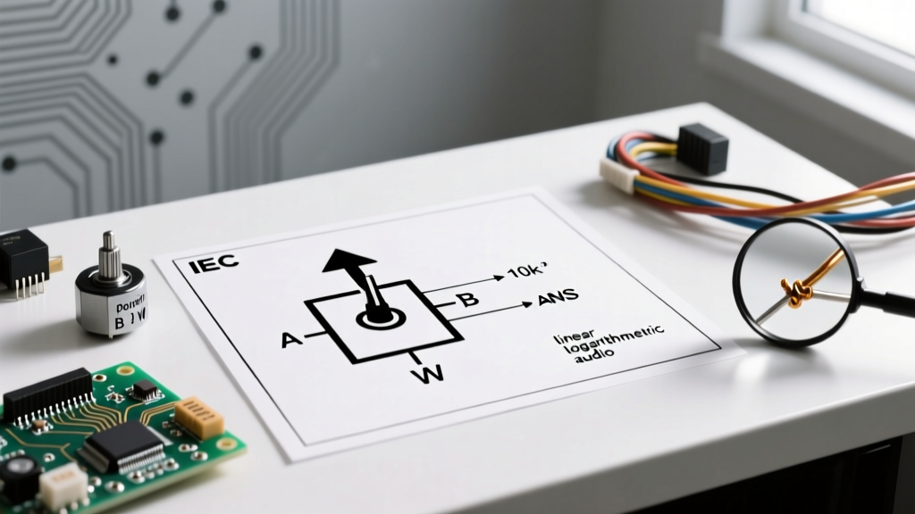
Schematic symbols often include annotations next to the resistor body to indicate the taper of the potentiometer. This is critical for circuit functionality, particularly in audio and sensor applications. As detailed in Electronics Tutorials, the taper defines the mathematical curve of the resistance change relative to the shaft rotation.
Linear Taper (Annotated as 'B' or 'LIN')
If the schematic specifies a 'B10K' potentiometer, the resistance changes at a constant, linear rate. At 50% shaft rotation, the wiper sits exactly at the 5K midpoint. This is mandatory for sensor calibration, oscilloscope time-base controls, and general-purpose voltage dividers.
Logarithmic / Audio Taper (Annotated as 'A' or 'LOG')
If the schematic specifies an 'A50K' potentiometer, the resistance curve is logarithmic. Human hearing perceives volume logarithmically, so an audio taper pot ensures that a 50% physical turn of the knob results in a perceived 50% volume level, even though the actual electrical resistance might be at 10% of the total track. Using a linear pot in an audio circuit will result in all the volume change happening abruptly in the first 20% of the knob's rotation.
Common Schematic Mistakes to Avoid
When drafting or reading the symbol for a potentiometer, watch out for these critical engineering errors:
- Wiper as a Power Source: Never use the wiper (Terminal 2) to supply high current to a load. The wiper contact has a parasitic resistance and can overheat or suffer contact bounce. The symbol implies voltage sensing, not power delivery.
- Ignoring the Maximum Wiper Current Rating: A standard 10K carbon track pot might be rated for 0.5W total power dissipation, but the wiper junction itself can fail at much lower localized currents. Always buffer the wiper output with an op-amp (voltage follower) if driving an ADC or a low-impedance load.
- Missing Ground Reference: In single-supply circuits, forgetting to tie Terminal 1 to the system ground will result in a floating output, causing erratic ADC readings on microcontrollers like the Arduino or STM32.
Summary
Mastering the symbol for a potentiometer goes far beyond recognizing a resistor with an arrow. It requires understanding the mechanical translation of the wiper, the implications of rheostat vs. voltage divider wiring, and the critical importance of taper annotations. By cross-referencing your schematic symbols with physical datasheets—such as those provided by All About Circuits—you ensure that your prototyping phase translates seamlessly into robust, noise-free circuit operation.