
The Anatomy of a 3-Terminal Variable Resistor
Before comparing the physical alternatives available on the market, we must establish the universal electrical standard. Regardless of the physical form factor, a standard potentiometer relies on three distinct connection points: two fixed terminals at the ends of a resistive track, and one movable wiper that slides across that track. Understanding the potentiometer pin layout is critical because misidentifying the wiper during prototyping will result in non-linear behavior, dead zones, or complete circuit failure.
In a standard schematic, the pins are typically designated as follows:
- Pin 1 (CCW): The counter-clockwise terminal. Usually tied to Ground (GND) in voltage divider applications.
- Pin 2 (Wiper): The variable output. This pin moves physically across the resistive element.
- Pin 3 (CW): The clockwise terminal. Usually tied to the reference voltage (VCC).
However, the physical manifestation of these three pins varies wildly depending on the mechanical alternative you choose for your project. A panel-mount audio pot looks nothing like a PCB-mounted trimmer, and their pinouts require entirely different wiring strategies.
Comparing Core Potentiometer Pin Layout Alternatives
When designing a custom PCB or wiring a perfboard prototype, engineers typically choose between three main mechanical alternatives. Each dictates a unique physical pin layout and footprint.
1. Standard Rotary Potentiometers (Panel & PCB Mount)
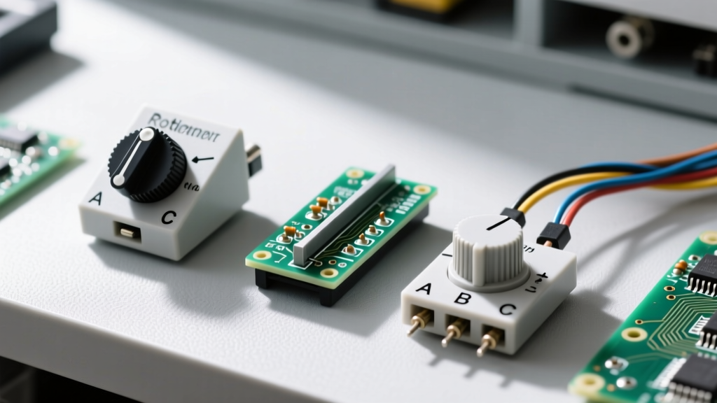
Rotary pots, such as the ubiquitous Alpha RD901F or Bourns PTV09A series, are the most common alternatives for user-facing interfaces (like volume knobs). The pin layout on PCB-mount rotaries usually features three pins in a straight line with a 5.0mm or 2.54mm pitch. Panel-mount variants, however, often feature staggered pins or large solder lugs that require flying leads. Prototyping Tip: If you are using a panel-mount rotary pot on a breadboard, the lug spacing will not fit. You must use a 3-pin JST pigtail or a dedicated breakout board to adapt the layout to a 2.54mm standard.
2. Linear Slide Potentiometers
Slide pots, like the Bourns PTA4543 series, are favored for audio mixing consoles and lighting desks. The pin layout here is highly deceptive for beginners. While the electrical logic remains the same (two end terminals, one wiper), the physical pins are often split between the bottom and the side of the housing to accommodate the long linear travel of the wiper mechanism. Pin 2 (the wiper) is frequently isolated on one side of the casing, while Pins 1 and 3 are grouped on the opposite edge. This spatial separation prevents accidental solder bridging but makes breadboarding nearly impossible without custom wiring harnesses.
3. Multi-Turn Cermet Trimmers
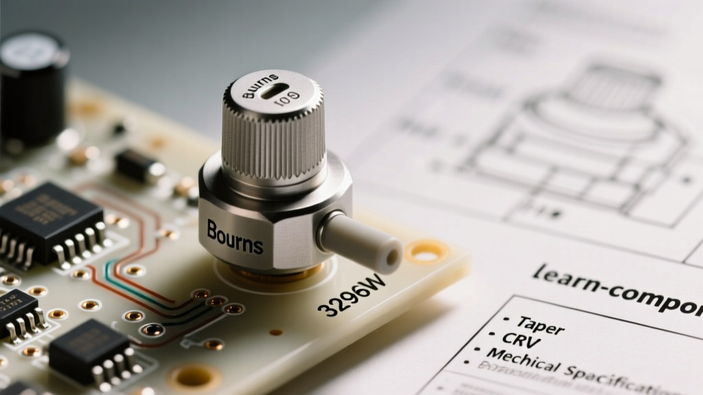
For precision calibration rather than user interaction, multi-turn trimmers like the Bourns 3296W are the gold standard. The 3296W features a top-adjust screw and a highly specific, breadboard-friendly pin layout. The three pins are arranged in a single row with a strict 2.54mm (0.1-inch) pitch. Pin 1 and Pin 3 are on the outer edges, and Pin 2 (the wiper) is dead center. This layout is standardized across almost all 3296W clones, making it the most predictable pinout in the component bin. However, the physical orientation of the "adjustment screw" relative to the pins means you must account for vertical clearance on your PCB.
Pinout Matrix: Footprint and Wiring Differences
To help you select the right alternative for your next build, refer to this comparison matrix detailing the physical and electrical nuances of each layout type.
| Alternative Type | Model Example | Pin Pitch / Layout | Wiper Position | Best Application | Avg. Price (USD) |
|---|---|---|---|---|---|
| PCB Rotary | Bourns PTV09A | 5.0mm inline | Center Pin | Microcontroller ADC inputs | $0.85 |
| Panel Rotary | Alpha RD901F | Staggered Lugs | Center Lug | Audio amplifiers, synths | $2.50 |
| Linear Slide | Bourns PTA4543 | Split (Side/Bottom) | Isolated Side Pin | Mixing desks, motor faders | $1.20 |
| Multi-Turn Trimmer | Bourns 3296W | 2.54mm inline | Center Pin | Precision voltage calibration | $1.50 |
The "Blind Pinout" Framework: Identifying Unmarked Wipers
A common frustration in the DIY electronics community is salvaging potentiometers from discarded equipment or buying unbranded surplus parts where the pin layout silkscreen has rubbed off. Guessing the pinout will likely result in connecting VCC directly to GND if you accidentally use the wiper as an end terminal and turn the shaft to the zero-ohm position.
Expert Troubleshooting Rule: Never apply power to an unverified potentiometer. Always map the pins using a digital multimeter (DMM) first.
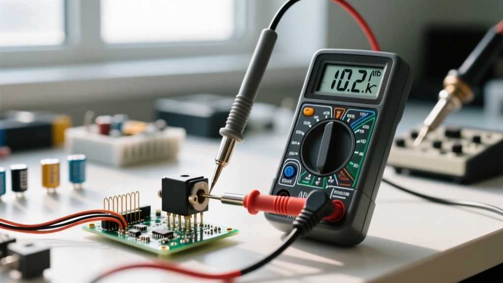
Follow this 3-step framework to identify the potentiometer pin layout blindly:
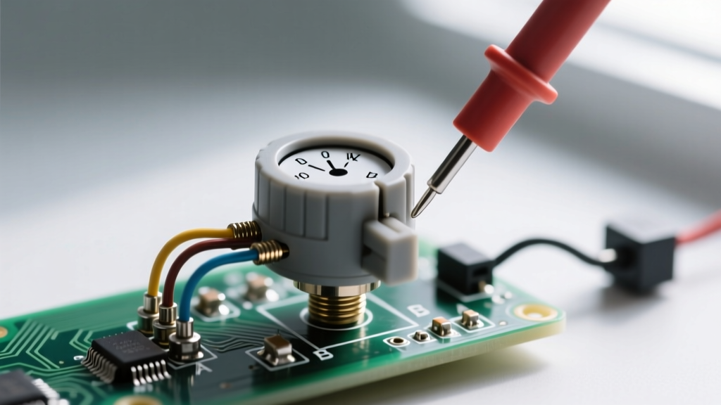
- Set your DMM to Resistance (Ohms). Measure the resistance between Pin A and Pin B. Turn the shaft or slide the fader. If the resistance changes, one of these pins is the wiper.
- Find the Fixed Track. Measure between all three permutations (1-2, 2-3, 1-3). The pair that shows a constant resistance value (e.g., exactly 10kΩ) regardless of shaft position represents Pins 1 and 3 (the fixed resistive track). The leftover pin is definitively Pin 2 (the wiper).
- Determine CW vs. CCW. Now that the wiper is identified, measure the resistance between the Wiper and Pin A. Turn the shaft clockwise. If the resistance drops to near 0Ω, Pin A is the CW terminal. If it rises to the maximum value, Pin A is the CCW terminal.
How Taper Impacts Pin Mapping Logic
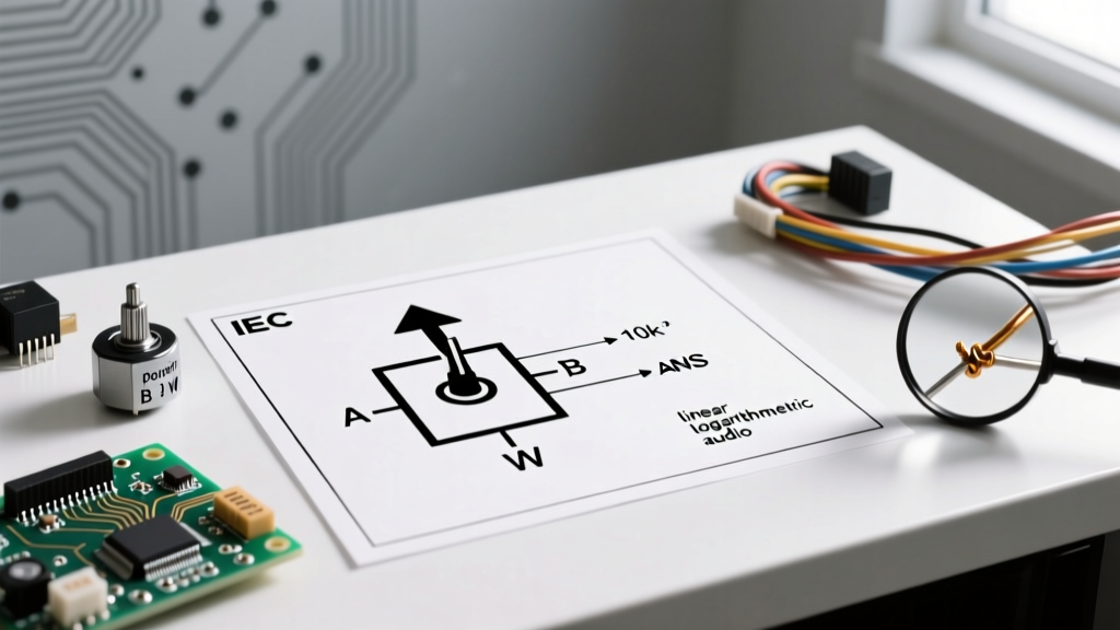
While the physical pin layout remains identical across tapers, the electrical mapping changes drastically between Linear (B-Taper) and Logarithmic/Audio (A-Taper) potentiometers. If you swap a 10kΩ Linear pot for a 10kΩ Audio pot in a microcontroller voltage divider circuit, your ADC readings will appear heavily skewed. At the physical midpoint of the shaft, a linear pot outputs exactly 50% of VCC. An audio taper pot, designed to match human hearing perception, might output only 15% to 20% of VCC at the physical midpoint. When designing firmware for reading potentiometer pin layouts via ADC, always check the taper silkscreen (usually an 'A' for Audio/Log or 'B' for Linear) and apply the appropriate software linearization curve.
Wiring Topologies: Rheostat vs. Voltage Divider
How you utilize the three pins defines your circuit topology. According to SparkFun's guide on voltage dividers, utilizing all three pins creates a variable voltage divider, which is ideal for feeding an analog signal into an Arduino or STM32 ADC pin. However, there is a vital alternative layout wiring trick every engineer must know: The Rheostat Configuration.
If you only need a variable resistor (e.g., to adjust the gain on an op-amp or dim a high-power LED via a constant current driver), you only use two pins: the Wiper and one End Terminal. Crucially, you must jumper the unused End Terminal directly to the Wiper. Why? If the wiper experiences a micro-disconnect due to dust or vibration (wiper bounce), the circuit would momentarily see infinite resistance. By tying the wiper to the unused track, a wiper bounce simply defaults the circuit to the maximum resistance of the track, preventing catastrophic open-circuit failures.
Real-World Failure Modes and Prototyping Pitfalls
Understanding the potentiometer pin layout is only half the battle; preserving it during assembly is the other. The most common failure mode in prototyping is thermal delamination. The resistive track in cheap carbon-composition pots is often printed on a fragile phenolic board inside a plastic housing. If you apply a 400°C soldering iron to the pins for more than 2-3 seconds, the heat travels down the pin, melts the internal plastic retaining clips, and shifts the resistive track. The physical pin layout remains intact, but the internal mechanical mapping is destroyed, resulting in a dead spot or a permanently shorted wiper.
Furthermore, when using slide pots in high-vibration environments (like robotics or automotive dashboards), the long, exposed carbon track is susceptible to dust ingress. This causes "scratchy" audio or jittery ADC readings. In these environments, engineers abandon standard carbon layouts in favor of conductive plastic or cermet alternatives, which offer vastly superior wiper contact stability despite a higher price point.
By carefully selecting the right mechanical alternative, verifying the wiper pin with a multimeter, and employing the rheostat jumper trick, you can ensure your variable resistance circuits remain robust, predictable, and noise-free.