
Introduction: Why Look at the Potentiometer Inside?
When troubleshooting a scratchy volume knob, calibrating a precision sensor, or designing a custom analog control interface, understanding the potentiometer inside its outer casing is critical. A potentiometer (or 'pot') is fundamentally a three-terminal resistor with a sliding or rotating contact that forms an adjustable voltage divider. While the exterior shaft and solder lugs are straightforward, the internal mechanics dictate the component's lifespan, noise floor, thermal stability, and power handling.
In this component identification guide, we will tear down the physical anatomy of the potentiometer inside its housing. By examining the resistive track materials, wiper contact dynamics, and internal taper geometries, you will learn how to identify unmarked components, diagnose internal mechanical failures, and select the exact potentiometer topology required for your next prototyping project.
The Core Anatomy: What Makes Up the Potentiometer Inside?
Regardless of whether you are working with a massive 5-watt wirewound rheostat or a microscopic surface-mount cermet trimmer, the internal architecture relies on three primary mechanical subsystems:
1. The Resistive Element (The Track)
The track is the physical heart of the component. It is a continuous strip or ring of resistive material deposited on a ceramic, plastic, or fiberglass substrate. The total resistance measured between the two outer terminals (Terminal 1 and Terminal 3) is determined entirely by the length, width, and material resistivity of this track. High-quality audio potentiometers, such as the renowned Alps RK27 series, use a meticulously applied carbon composition track to ensure ultra-low current noise.
2. The Wiper (Contact Arm)
The wiper is a spring-loaded metal contact that rides along the resistive track. It is connected to the center terminal (Terminal 2). The physical pressure the wiper exerts on the track—typically measured in grams—is a delicate engineering compromise. Too little pressure, and the wiper will 'lift off' during vibration, causing momentary open circuits and audible pops. Too much pressure, and the wiper will prematurely wear away the resistive material, generating conductive dust that shorts adjacent sections of the track.
3. The Terminals and Commutator
Inside the housing, the track terminates at two stamped metal stakes or soldered joints that connect to the exterior pins. In rotary pots, a brass or phosphor-bronze commutator ring often bridges the physical rotation of the shaft to the stationary electrical terminals, allowing for continuous 360-degree rotation in specialized servo-feedback pots.
Identifying the Resistive Track Material
If you find an unmarked potentiometer on a salvaged PCB, or if you need to verify a manufacturer's datasheet, identifying the track material is your first step. According to Electronics Tutorials, the track material dictates the component's resolution, thermal coefficient, and acoustic noise profile. Here is how to identify the four dominant internal materials:
Carbon Composition
Visually, carbon tracks appear as a dull, dark grey or black painted line on a phenolic or ceramic substrate. They are incredibly common in consumer audio equipment and guitar pedals. While cheap to manufacture, carbon tracks suffer from high current noise and are highly susceptible to humidity and mechanical wear. If you open a standard Alpha 9mm pot, you will almost certainly find a carbon track.
Cermet (Ceramic-Metal)
Cermet tracks are created by firing a mixture of glass, ceramic, and metal oxides onto a substrate at extreme temperatures. They appear as a glossy, dark brown or reddish-brown stripe. Cermet is the standard for precision trimpots (like the ubiquitous Bourns 3296 series) because it offers exceptional thermal stability (often less than 100 ppm/°C) and can survive multiple high-temperature soldering reflow cycles without drifting.
Wirewound
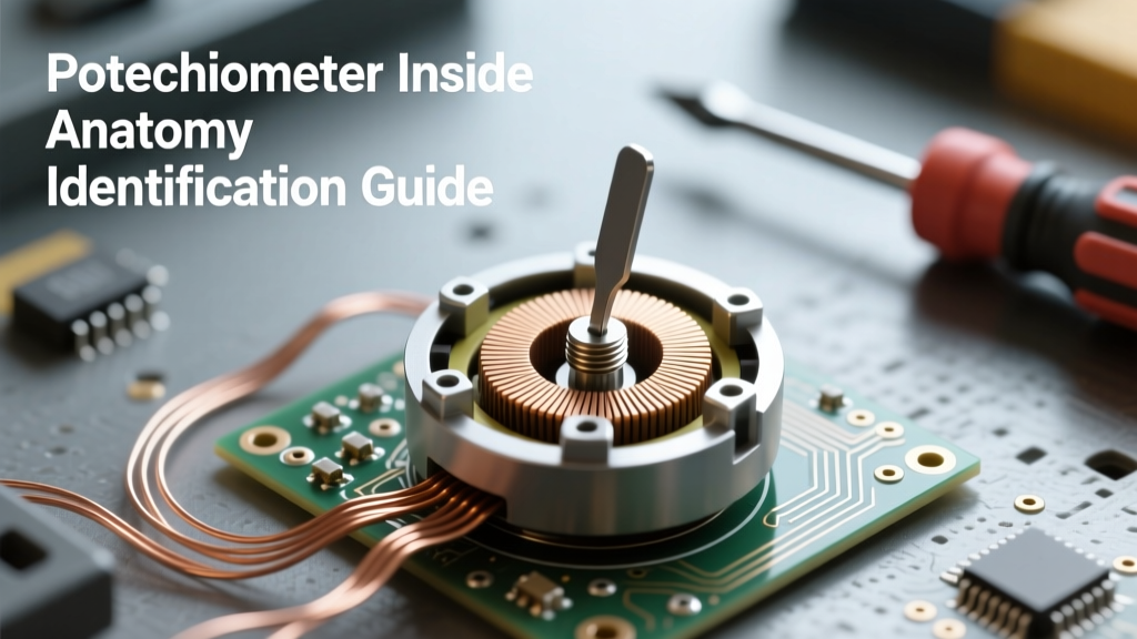
Opening a high-power potentiometer reveals a toroidal core wrapped tightly with fine resistance wire, typically Nichrome or a similar nickel-chromium alloy. The wiper slides across the exposed top of the wire loops. Wirewound pots handle massive power loads (up to 100W+ in chassis-mount variants) but suffer from a fundamental flaw: finite resolution. The wiper must 'jump' from one wire loop to the next, creating a stepped output rather than a truly continuous analog sweep.
Conductive Plastic
Conductive plastic tracks are formulated by embedding carbon or metal particles into a high-grade polymer resin. They offer the highest lifespan (often exceeding 1 million rotational cycles) and the smoothest resolution. They are visually difficult to distinguish from carbon but feel significantly smoother under rotational torque and are predominantly found in high-end studio mixing consoles and aerospace joysticks.
Track Material Comparison Matrix
| Material | Resolution | Current Noise | Lifespan (Cycles) | Primary Application |
|---|---|---|---|---|
| Carbon | Good | High | 15,000 - 50,000 | Consumer Audio, Guitars |
| Cermet | Excellent | Low | 200 - 500 | Precision Calibration, Trimpots |
| Wirewound | Poor (Stepped) | Very Low | 50,000 - 100,000 | High-Power Motor Control |
| Conductive Plastic | Infinite | Ultra-Low | 1,000,000+ | Studio Faders, Joysticks |
Taper Identification: Linear vs. Logarithmic Internals
The 'taper' of a potentiometer defines the mathematical relationship between the physical shaft angle and the electrical resistance output. But how is this achieved inside the physical component? The secret lies in the geometry of the resistive track.
Linear Taper (B-Taper)
If you open a linear potentiometer, you will observe that the resistive track is painted or deposited with a perfectly uniform width and thickness from end to end. Because the cross-sectional area of the resistor is constant, every degree of shaft rotation yields an identical change in resistance. This is mandatory for applications like motor speed controls, panning circuits, and sensor calibration, as detailed by All About Circuits.
Logarithmic / Audio Taper (A-Taper)
Human hearing perceives volume logarithmically, meaning a linear increase in electrical power sounds like a diminishing increase in volume. To compensate, audio potentiometers use a non-uniform track. Inside an audio pot, the resistive material is painted thicker or wider on one half of the arc, and thinner on the other. Alternatively, manufacturers use two distinct resistive inks with different specific resistivities, meeting at a central crossover point. When measuring an unmarked pot with a multimeter, rotating the shaft to the exact mechanical center will yield roughly 50% resistance on a linear pot, but only 10% to 15% resistance on a logarithmic audio pot.
Common Internal Failure Modes and Troubleshooting
Understanding the potentiometer inside allows you to accurately diagnose failures that mimic other circuit faults. Here are the most common internal mechanical breakdowns:
- Track Wear and Carbon Dust: Over thousands of rotations, the wiper physically abrades the track. In carbon pots, this creates a fine conductive dust that settles in the gaps of the track, causing micro-shorts and erratic voltage spikes. This manifests as the classic 'scratchy' noise in guitar amplifiers.
- Wiper Lift-Off (Dead Spots): If the internal spring tension fatigues, or if the pot is subjected to mechanical shock, the wiper momentarily loses contact with the track. In a volume control, this causes audio dropouts. In a microcontroller voltage-divider circuit, this causes the ADC pin to float, resulting in wild, unpredictable data readings.
- Terminal Staking Failure: The internal connection between the resistive track and the metal terminal pin relies on a mechanical crimp or a high-temperature solder joint. Thermal cycling can cause these joints to develop micro-fractures, resulting in an 'open circuit' reading between Pin 1 and Pin 3, even if the track itself is perfectly intact.
Expert Troubleshooting Tip: Never spray standard WD-40 or harsh solvents into an open potentiometer. These fluids strip the internal factory lubricants applied to the wiper shaft and can dissolve the phenolic binders in carbon tracks. If a carbon pot is scratchy, use a specialized contact cleaner with a built-in dielectric lubricant, such as DeoxIT F5, applied sparingly to the track via a micro-brush.
Teardown Walkthrough: Safely Opening a Sealed Pot
To physically inspect the potentiometer inside, you must bypass the manufacturer's housing. Most modern panel-mount pots use either a metal rear casing or a molded plastic shell.
For metal-cased pots (common in Bourns and CTS models), the rear plate is held on by four small metal tabs folded over the edge of the front plate. Use a small flathead jeweler's screwdriver to gently pry these tabs upward by no more than 45 degrees. Do not bend them completely flat, as the metal will fatigue and snap when you attempt to re-crimp them. Once the tabs are clear, the rear shield will lift off, revealing the track and wiper assembly.
For plastic-cased pots (like the Alps RK09 series), the housing is typically ultrasonically welded or snapped together with internal barbs. These are largely considered non-serviceable. If you must inspect the internals of a failed plastic pot for forensic failure analysis, carefully score the seam with a hobby knife and apply gentle torsional pressure to pop the ultrasonic welds. Note that reassembling a snapped plastic pot is nearly impossible without compromising its structural integrity and introducing rotational wobble.
By mastering the internal architecture of these components, you transition from simply swapping out broken parts to engineering robust, long-lasting analog interfaces. Whether you are specifying a cermet trimmer for a high-temperature aerospace sensor or restoring a vintage analog synthesizer, knowing the potentiometer inside is the hallmark of a true electronics professional. For further reading on precision component selection, consult the Bourns Potentiometers technical library to review specific tolerance and lifecycle datasheets.