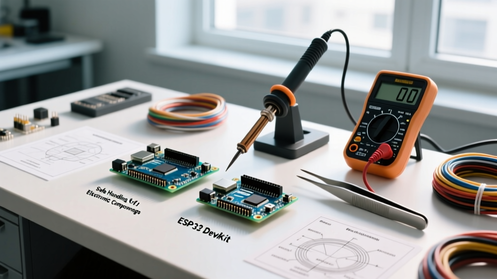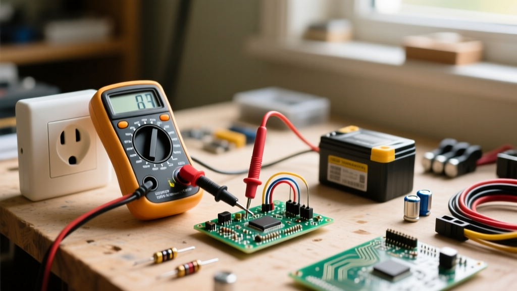

When makers, hobbyists, and engineering students first ask, 'what is an oscilloscope used for,' the simplest answer is that it acts as the eyes of your electronics workbench. While a multimeter gives you a single numerical snapshot of a circuit's state, an oscilloscope (often abbreviated as O-scope) graphs voltage over time. This visual representation is the difference between knowing a signal exists and understanding exactly how that signal behaves, degrades, or interacts with other components.
If you are transitioning from basic Arduino projects to designing custom printed circuit boards (PCBs), debugging high-frequency digital buses, or building analog audio synthesizers, understanding what an oscilloscope is used for in practical scenarios is the single biggest leap you can make in your DIY electronics journey. In this guide, we will bypass the dense academic theory and focus on the real-world applications, specific project use-cases, and buying considerations for the modern home lab.
The Core Function: Visualizing Voltage Over Time
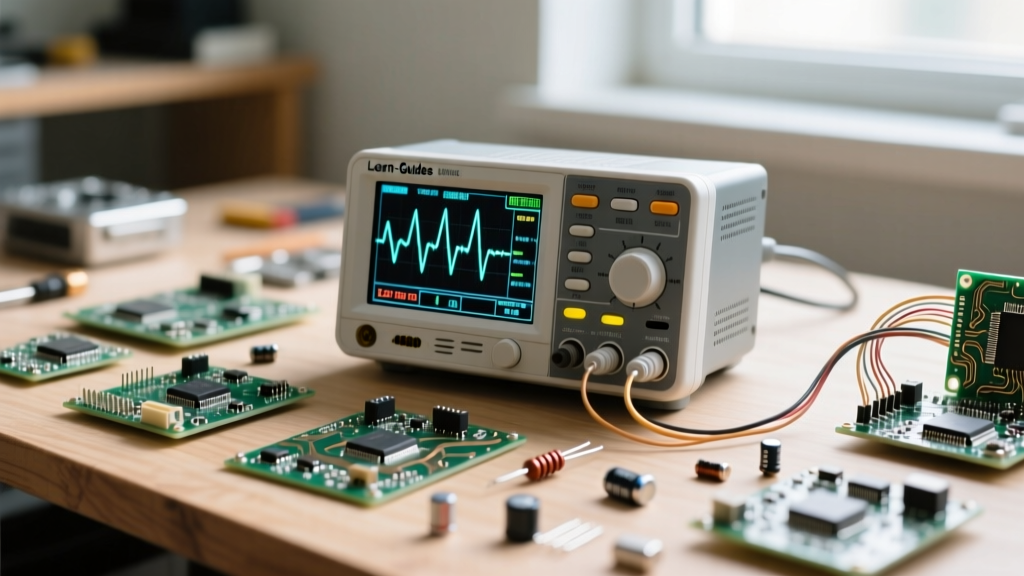
At its most fundamental level, an oscilloscope maps voltage (Y-axis) against time (X-axis). According to Tektronix's foundational guide to oscilloscopes, the device captures electrical signals and renders them as waveforms on a digital or cathode-ray display. For a DIYer, this means you can physically see the shape of an alternating current (AC) sine wave, the sharp edges of a digital square wave, or the chaotic noise riding on a supposedly clean DC power rail.
The magic of the O-scope lies in its triggering system. Without a trigger, a repeating waveform would look like a blurry, scrolling mess across the screen. The trigger tells the oscilloscope to start drawing the graph only when the voltage crosses a specific threshold (e.g., 2.5V rising), effectively 'freezing' repetitive signals so you can measure their frequency, duty cycle, and amplitude with precision.
5 Practical DIY Projects Where an Oscilloscope is Essential
1. Debugging Microcontroller PWM Signals
When you use the analogWrite() function on an Arduino or configure the LEDC peripheral on an ESP32, you are not actually outputting an analog voltage. You are generating a Pulse Width Modulation (PWM) square wave. If your DIY motor controller is stuttering or your LED strip is flickering, a multimeter will only show you an averaged, largely useless DC voltage. An oscilloscope allows you to measure the exact PWM frequency (e.g., 490Hz vs 20kHz) and verify the duty cycle, ensuring your microcontroller is outputting the precise timing required by your ESC or LED driver.
2. Decoding Digital Communication Protocols
Modern DIY projects rely heavily on sensor modules communicating via I2C, SPI, or UART. When an I2C temperature sensor fails to return data to your Raspberry Pi or microcontroller, a logic analyzer can help, but an oscilloscope reveals the analog reality of the digital bus. You can use the scope to check if your pull-up resistors are correctly sized by observing the rise times of the SDA and SCL lines. If the edges of your square waves look like sluggish shark fins, your parasitic capacitance is too high, and you need to lower your pull-up resistance or reduce your bus speed.
3. Analyzing Power Supply Ripple and Noise
Suppose you are building a DIY linear power supply using an LM7805 voltage regulator. Your multimeter reads a perfect 5.00V. However, your sensitive audio amplifier circuit is emitting a high-pitched whine. By switching to an oscilloscope and setting the input to AC coupling with a highly sensitive vertical scale (e.g., 10mV/div), you can visualize the high-frequency switching noise or mains ripple that the multimeter's low-pass filtering completely ignored. This is critical for DIY audio and precision sensor projects.
4. Audio Circuit Troubleshooting and Signal Tracing
For DIY guitar pedal builders and analog synthesizer enthusiasts, the oscilloscope is an indispensable diagnostic tool. If a fuzz or overdrive pedal is producing unwanted artifacts, you can inject a clean 1kHz sine wave from a function generator and trace the signal through each transistor or op-amp stage. By observing where the waveform clips asymmetrically or where high-frequency parasitic oscillation begins, you can adjust biasing resistors or add compensation capacitors to tame the circuit. SparkFun's oscilloscope tutorial highlights how visualizing audio clipping helps designers calculate Total Harmonic Distortion (THD) on the fly.
5. Tuning Switched-Mode Power Supplies (SMPS)
Designing a custom buck or boost converter is a rite of passage for advanced DIYers. These circuits switch MOSFETs on and off at hundreds of kilohertz. An oscilloscope is mandatory to observe the switch node (SW) ringing. Excessive voltage spikes during the MOSFET turn-off phase can destroy your components or cause massive Electromagnetic Interference (EMI). By using your scope to measure these nanosecond spikes, you can design an effective RC snubber network to dampen the ringing and protect your circuit.
Multimeter vs. Oscilloscope: When to Use Which
A common mistake among beginners is thinking an oscilloscope replaces a multimeter. In reality, they are complementary tools. Here is a practical framework for deciding which tool to reach for on your workbench:
| Measurement Scenario | Digital Multimeter (DMM) | Oscilloscope |
|---|---|---|
| Checking Battery Voltage | Ideal. Provides high-precision, stable numerical readout. | Overkill. Visual confirmation is unnecessary. |
| Verifying Continuity | Essential. Audible beep for quick trace checking. | Not applicable. |
| Measuring PWM Duty Cycle | Poor. Will only display a confusing average DC voltage. | Ideal. Visually calculates exact on/off time ratios. |
| Observing Sensor Noise | Useless. Internal averaging filters hide high-frequency noise. | Essential. AC coupling reveals millivolt-level anomalies. |
| Debugging I2C/SPI Clocks | Useless. Cannot track rapid logic state transitions. | Ideal. Captures and decodes digital bus protocols. |
Choosing Your First DIY Oscilloscope: Key Specs
When shopping for your first scope, the specifications can be overwhelming. According to All About Circuits, understanding bandwidth and sample rate is crucial to avoid buying a tool that bottlenecks your projects.
- Bandwidth: This dictates the highest frequency signal the scope can accurately measure without attenuating it. For general DIY microcontroller work and audio, 50MHz is sufficient. If you plan to debug high-speed USB, DDR memory, or fast-switching SMPS circuits, aim for 100MHz to 200MHz.
- Sample Rate: The Nyquist theorem states you need to sample at least twice the frequency of your signal, but in practice, you want a sample rate at least 5 to 10 times your bandwidth. A 100MHz scope should have a minimum of 1 GSa/s (Giga-samples per second).
- Channel Count: Two channels are the absolute minimum for comparing an input vs. an output signal. However, 4-channel scopes (like the legendary Rigol DS1054Z) are highly recommended for DIYers decoding SPI or I2C buses, as you can monitor Clock, Data, Chip Select, and an interrupt pin simultaneously.
- Memory Depth: This determines how much of a signal's history the scope can store before the screen refreshes. Deeper memory allows you to zoom in on a tiny microsecond glitch that happened seconds ago while capturing a long serial data stream.
Critical Safety: The Grounding Trap for DIYers
There is a severe safety hazard that every DIYer must understand before connecting a probe to a circuit: the oscilloscope ground clip is tied directly to earth ground via the power cord's third prong.
Never use a standard passive oscilloscope probe to measure mains-referenced circuits, such as the primary side of a non-isolated switched-mode power supply or a wall-dimmer switch, without an isolation transformer or a specialized high-voltage differential probe. Connecting the ground clip to a live mains voltage will create a dead short through the oscilloscope, resulting in an explosive failure, destroyed equipment, and severe risk of electrocution.
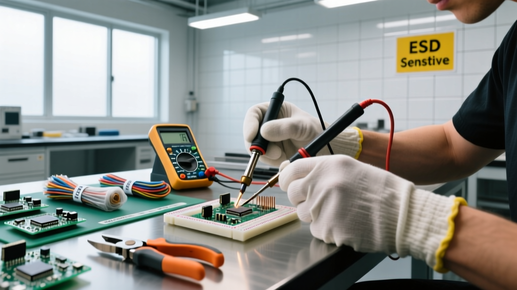
For low-voltage DC DIY projects (like Arduino, Raspberry Pi, or 12V automotive circuits), this earth-ground connection is generally safe and actually helps establish a common ground reference between your scope and your device under test (DUT). Always connect the ground clip first, and ensure your DUT is either battery-powered, isolated, or shares a common earth ground with the oscilloscope.
Mastering the 10x Probe Compensation
Before you measure any high-frequency DIY signal, you must compensate your probe. Most DIYers use 10x passive probes, which contain an internal RC (resistor-capacitor) network to reduce the capacitive load on your circuit. If the internal trimmer capacitor is not matched to your specific oscilloscope channel's input capacitance, your square waves will look distorted.
To fix this, attach the probe to the 1kHz square wave reference terminal on the front panel of your scope. Adjust the tiny screw on the probe's compensation box using a non-conductive trimmer tool until the corners of the square wave are perfectly flat. An under-compensated probe will show rounded corners (missing high frequencies), while an over-compensated probe will show ringing overshoots on the edges, leading to false readings when debugging fast digital logic.
Conclusion
Understanding what an oscilloscope is used for transforms you from a parts-assembler into a true circuit designer. Whether you are hunting down parasitic oscillations in a DIY tube amplifier, verifying the timing of a custom I2C sensor array, or simply ensuring your buck converter is operating efficiently, the oscilloscope provides the empirical truth of your electronics. Invest in a capable entry-level scope, master the triggering controls, respect the grounding rules, and your home lab capabilities will expand exponentially.