
The Internal Anatomy: How Breadboards Work Beneath the Surface
When a prototype circuit suddenly drops offline or behaves erratically, the immediate instinct for most makers is to blame the microcontroller code, a fried integrated circuit, or a faulty sensor. However, the physical interconnect is overwhelmingly the most common culprit. To effectively troubleshoot a misbehaving prototype, you must first understand exactly how breadboards work beneath the plastic facade.
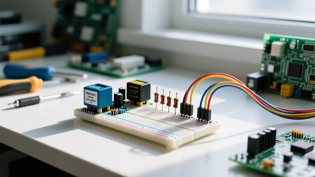
Standard solderless breadboards utilize a 0.1-inch (2.54 mm) pitch grid, matching the pin spacing of standard DIP (Dual In-line Package) chips. Beneath the perforated ABS plastic shell lies a complex matrix of stamped metal clips. Premium breadboards utilize phosphor bronze clips with a gold flash coating. This material combination provides excellent spring retention, low insertion force, and minimal contact resistance. Conversely, budget boards often substitute this with nickel-plated steel or tin-plated brass, which suffer from faster oxidation, higher contact resistance, and rapid mechanical degradation over time.
The Terminal Strip Architecture
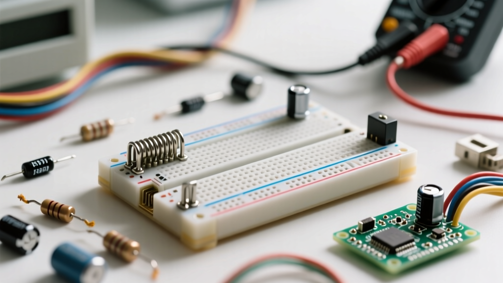
The main prototyping area of the breadboard is divided into two distinct halves by a center isolation trench. Each half consists of 5-hole terminal strips (typically rows labeled a-e and f-j). Internally, these five holes are clamped by a single continuous metal spring clip. The center trench physically breaks this connection, allowing dual-inline package integrated circuits to straddle the gap without shorting opposing pins together. If you are troubleshooting a short circuit on a newly placed IC, always verify that the chip is seated perfectly across this trench; a misaligned chip resting entirely on one side will instantly short adjacent output pins to ground or VCC.
Power Bus Discontinuities and the Split-Rail Trap
The outer rails, typically marked with red and blue silkscreen lines, run vertically along the edges and are designed to distribute power and ground. A critical, often-overlooked detail in modern half-sized and full-sized boards is the split power rail. Many manufacturers introduce a physical gap in the internal metal strip at the exact center of the board, indicated by a break in the colored silkscreen line. This feature is designed for dual-voltage systems (e.g., +5V on top, +12V on the bottom). Failing to bridge this gap with a physical jumper wire is one of the most frequent reasons a breadboarded op-amp, motor driver, or sensor array fails to power up on the bottom half of the board.
Diagnosing the Ghost in the Machine: Connection Failure Modes
Understanding the mechanical realities of the board allows us to categorize the most common failure modes that plague prototyping environments.
1. Contact Resistance and Oxidation
Every mechanical connection introduces a small amount of resistance. In a pristine, gold-plated breadboard, this might be 10 to 50 milliohms per junction. However, as the clips are exposed to ambient humidity and repeated insertions of oxidized component leads, this resistance can climb into the single or double-digit ohms. In low-current digital logic circuits, a 5-ohm contact resistance is invisible. But in analog sensor networks or high-current LED drivers, this resistance creates a voltage divider effect, starving your components of the required operating voltage. If your analog readings are drifting or your LEDs are dim, suspect contact resistance before blaming the code.
2. Wire Gauge Mismatch and the Grip Problem
Breadboard clips are engineered specifically for 22 AWG (0.64 mm) solid-core copper wire. A frequent troubleshooting nightmare occurs when a builder uses 24 AWG wire (often harvested from old Cat5 ethernet cables). Because 24 AWG is significantly thinner (0.51 mm), it fails to engage the spring clip properly, resulting in intermittent connections that break the moment the desk is bumped. Conversely, forcing 20 AWG wire or thick component leads into the holes will permanently stretch and deform the phosphor bronze springs, ruining that specific 5-hole strip for all future 22 AWG wires.
3. Mechanical Deformation from Pliers
Never use needle-nose pliers to extract a stubborn component or wire from a breadboard. Pulling with pliers applies lateral torque to the internal clip, bending it away from the centerline of the hole. Once a clip is bent, it will no longer apply adequate normal force to the inserted wire, creating an invisible 'dead hole' that will cause endless headaches in future projects.
High-Frequency Headaches: Parasitic Capacitance in Solderless Boards
One of the most misunderstood limitations of solderless prototyping is parasitic capacitance. Because the internal metal strips run parallel to one another in close proximity, they form unintended capacitors. According to extensive testing documented by SparkFun's Breadboard Tutorial, adjacent terminal strips typically exhibit between 2pF and 5pF of parasitic capacitance.
While 5 picofarads sounds negligible, it becomes a massive impedance issue at higher frequencies. The capacitive reactance ($X_c$) is calculated as $X_c = \frac{1}{2 \pi f C}$. At a standard I2C speed of 400 kHz, the impedance is roughly 80 kΩ, which is generally manageable. However, if you are prototyping a 10 MHz SPI bus or an RF oscillator, the impedance drops to approximately 3.18 kΩ. This low-impedance bridge causes severe signal crosstalk, ringing, and data corruption. If your high-speed digital protocol is failing on a breadboard but works perfectly on a soldered PCB, parasitic capacitance is your primary suspect.
Step-by-Step Troubleshooting Framework for Breadboarded Circuits
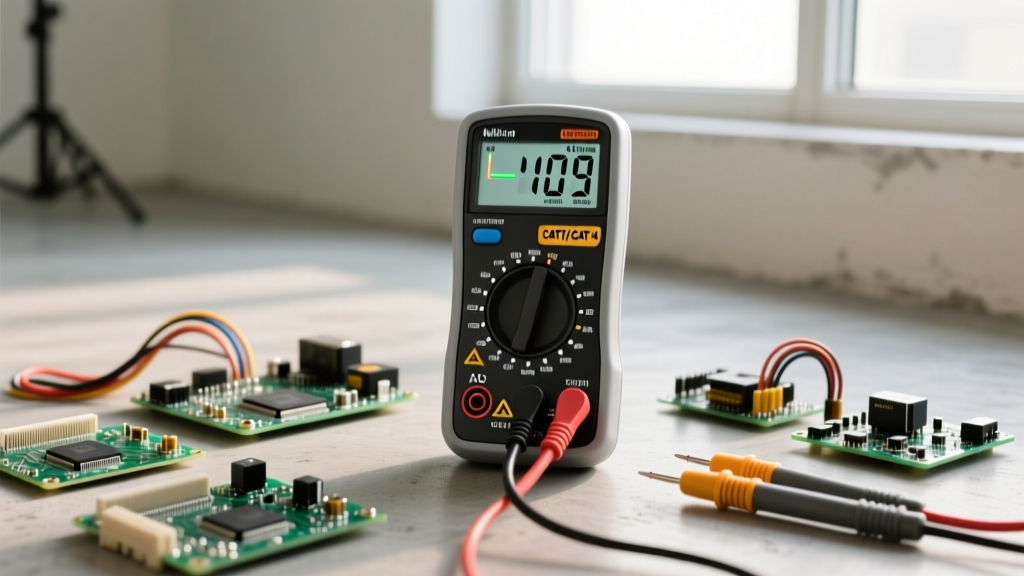
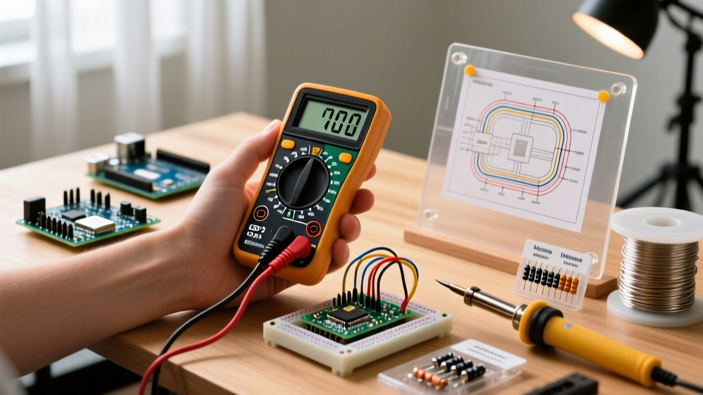
When a circuit fails to operate, abandon the "randomly push wires" approach. Implement this systematic diagnostic framework using a digital multimeter (DMM).
The Continuity Test Trap
Most hobbyists rely on the audible "beep" of their multimeter's continuity mode. This is a critical mistake. The beep threshold on most budget DMMs triggers anywhere between 10 and 30 ohms. A breadboard connection measuring 15 ohms will beep, convincing you the connection is good, when in reality, 15 ohms of contact resistance is more than enough to cause a voltage brownout in a microcontroller. Always switch your DMM to the lowest resistance range (e.g., 200Ω) and read the actual numeric value. A healthy breadboard junction should read between 0.1Ω and 0.5Ω. Anything above 2.0Ω indicates a failing clip or a dirty component lead.
Common Faults and Resolutions Matrix
| Fault Type | Primary Symptom | Diagnostic Method | Resolution |
|---|---|---|---|
| Clip Oxidation | Intermittent signal drops when the board is lightly tapped or vibrated. | Monitor DMM resistance reading while applying lateral pressure to the inserted wire. | Clean component leads with isopropyl alcohol; apply DeoxIT contact cleaner to the board, or retire the board. |
| Wire Gauge Mismatch | Wire pulls out with zero resistance; erratic ADC readings. | Measure wire diameter with calipers. 22 AWG is 0.64mm; 24 AWG is 0.51mm. | Discard thin wire; strip and use strictly 22 AWG solid-core copper wire for all jumpers. |
| Split Rail Gap | Bottom half of the circuit is completely dead; sensors read 0V. | Visual inspection of the red/blue silkscreen for a center break; DMM voltage check across the gap. | Install a physical 22 AWG jumper wire across the center gap to unify the power bus. |
| Deformed Clips | Specific hole refuses to grip any wire; localized dead zones. | Insert a known-good 22 AWG wire and perform a gentle vertical pull-test. | Abandon the specific 5-hole strip; route jumper wires to an adjacent, unused terminal strip. |
Best Practices for Reliable Prototyping and Clip Longevity
To minimize troubleshooting time and extend the lifespan of your prototyping gear, adopt these professional habits:
- Prep Component Leads: Component leads straight out of the anti-static bag are often oxidized. Lightly scrape them with a fiberglass scratch pen or sandpaper before inserting them into the breadboard to ensure optimal metal-to-metal contact.
- Avoid Stranded Wire: Never jam bare stranded wire into a breadboard hole. The individual copper strands will splay out, bend the internal clips, and cause short circuits with adjacent rows. If you must use stranded wire, solder a small piece of solid 22 AWG wire to the end as a makeshift pin, or use crimped bootlace ferrules.
- Strategic Placement: As noted by experts at Electronics Notes, keep high-current paths (like motor drivers and power supplies) as far away from sensitive analog signal paths as possible to minimize both resistive voltage drops and magnetic interference.
- Know When to Solder: A breadboard is a prototyping tool, not a final deployment platform. If your circuit involves high-frequency RF, precision analog audio, or currents exceeding 1 Amp, the inherent resistance and parasitics of the breadboard will always work against you. Transition to a soldered perfboard or custom PCB as soon as the logic is verified.
Pro-Tip: Keep a can of compressed air and a soft anti-static brush on your workbench. Breadboards act as magnets for clipped wire offcuts, dust, and metallic debris. A tiny strand of copper wire lodged inside a terminal hole can cause an intermittent short circuit that is nearly impossible to diagnose visually. Always flush your boards with compressed air before starting a new build.
By shifting your perspective from viewing the breadboard as a flawless conductor to treating it as a complex mechanical component with specific tolerances and failure modes, you will drastically reduce your debugging time. Understanding how breadboards work on a microscopic level is the hallmark of a mature electronics hobbyist and a highly efficient hardware engineer.