
The Foundation of DIY Electrical Work: Understanding Voltage
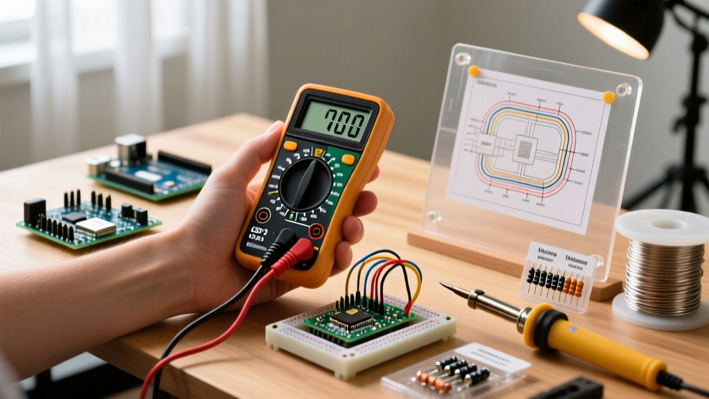
Every DIY electrical project, from wiring a smart home thermostat to debugging a custom Arduino sensor array, begins with a single fundamental skill: understanding electrical potential. Voltage is the pressure from an electrical circuit's power source that forces charged electrons (current) through a conducting loop. If you are wondering how to check voltage with a multimeter, you are taking the critical first step toward electrical self-reliance and safe troubleshooting.
Whether you are verifying that a wall outlet is properly energized before installing a new fixture, or ensuring your 5V logic rail isn't sagging under the load of a DIY LED matrix, a digital multimeter (DMM) is your primary diagnostic tool. This comprehensive DIY guide will walk you through the exact methodologies, safety protocols, and real-world troubleshooting scenarios required to master voltage testing in both alternating current (AC) and direct current (DC) environments.
The Anatomy of a Voltage Test: AC vs. DC
Before touching any probes, you must understand the two distinct types of voltage you will encounter in DIY projects. Multimeters separate these into two distinct dial settings, usually denoted by specific symbols.
- AC Voltage (V~ or VAC): Alternating Current changes direction periodically. This is the power delivered to your home by the utility grid. In North America, standard wall outlets provide nominally 120V AC at 60Hz, while in Europe and many other regions, it is 230V AC at 50Hz. You will use this setting for testing outlets, switches, and home wiring.
- DC Voltage (V⎓ or VDC): Direct Current flows in a single, constant direction. This is the power provided by batteries, solar panels, and the internal voltage regulators of microcontrollers like the Raspberry Pi or Arduino. You will use this setting for testing battery health, automotive electrical systems, and custom PCB power rails.
Choosing the Right Multimeter for DIY Voltage Checks
Not all multimeters are created equal. When learning how to check voltage with a multimeter, the quality of your tool dictates both your safety and the accuracy of your readings. Below is a comparison of three popular models across different DIY budget tiers.
| Model | Type | CAT Rating | Approx. Price | Best DIY Application |
|---|---|---|---|---|
| Fluke 117 | True-RMS | CAT III 600V | $180 - $200 | Professional home wiring, HVAC, heavy DIY |
| Klein Tools MM400 | Auto-Ranging | CAT III 600V | $45 - $55 | General home repair, basic electronics |
| AstroAI AM33D | Manual-Ranging | CAT II 600V | $12 - $18 | Low-voltage DC electronics, battery testing |
For any DIYer working with mains AC voltage, an auto-ranging True-RMS meter with a minimum CAT III rating is highly recommended. True-RMS (Root Mean Square) ensures accurate readings even when the AC waveform is distorted by non-linear loads like LED drivers or computer power supplies.
Safety First: Understanding CAT Ratings and Arc Flash
When testing live AC mains, safety is non-negotiable. The International Electrotechnical Commission (IEC) defines Measurement Categories (CAT) to specify the transient overvoltage withstand capability of a meter. According to Fluke's official safety guidelines, a CAT III multimeter is required for testing fixed wiring, distribution panels, and hardwired appliances. A CAT II meter is only safe for plug-in appliances and standard receptacles. Never use a cheap, unrated multimeter from an online marketplace to test your home's breaker panel; a transient voltage spike can cause the meter to explode in your hands. Always wear ANSI-rated safety glasses when probing live AC circuits.
Step-by-Step: How to Check Voltage With a Multimeter (AC Outlets)
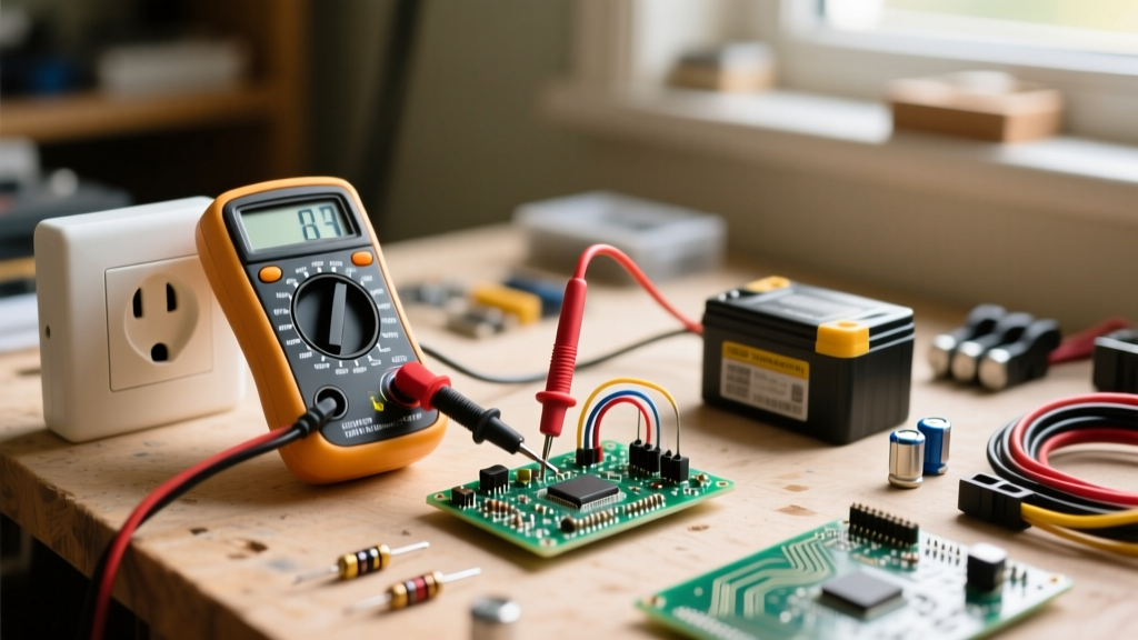
Testing a standard North American 120V AC NEMA 5-15 receptacle is a common DIY task. Follow these exact steps to ensure a safe and accurate reading.
- Inspect Your Probes: Ensure the insulation on your test leads is free of cracks or exposed wire. The finger guards must be intact.
- Set the Dial: Turn the multimeter dial to AC Voltage (V~). If your meter is manual-ranging, select the 200V or 600V scale (never select a scale lower than the expected voltage).
- Insert the Probes: Plug the black probe into the COM (Common) port and the red probe into the VΩ (Volts/Ohms) port.
- Test Hot to Neutral: Insert the red probe into the shorter vertical slot (Hot) and the black probe into the longer vertical slot (Neutral). A healthy reading should be between 114V and 126V.
- Test Hot to Ground: Move the black probe to the U-shaped Ground slot. The reading should remain virtually identical to the Hot-Neutral reading (approx. 120V).
- Test Neutral to Ground: Insert the probes into the Neutral and Ground slots. This reading should be very low, typically under 2V. A reading higher than 3V indicates a potential wiring fault, such as an overloaded neutral or a missing ground bond.
Step-by-Step: Testing DC Voltage in Electronics and Batteries
DC voltage testing is the lifeblood of DIY electronics. Whether you are verifying a 9V alkaline battery or checking the 5V rail on a custom Arduino Nano shield, the process is straightforward but requires attention to polarity.
Testing a Standard Battery
Set your multimeter to DC Voltage (V⎓). For a standard 9V battery, select the 20V range on a manual-ranging meter. Touch the red probe to the positive (+) terminal and the black probe to the negative (-) terminal. A fresh alkaline 9V battery will typically read around 9.5V. If the reading drops below 8.0V under no load, the battery is effectively dead for high-drain DIY applications. If you reverse the probes, a digital multimeter will simply display a negative sign (e.g., -9.5V), which is harmless. However, never do this with an analog needle meter, as the needle will violently peg backward and bend.
Probing Microcontroller Logic Rails
When debugging a DIY PCB or breadboard, you are often looking for precise DC logic levels. To check the 5V rail on an Arduino, set the meter to DC Voltage. Place the black probe firmly on any GND (Ground) pin or the metal shield of a USB connector. Place the red probe on the 5V output pin. A reading of 4.95V to 5.05V is ideal. If you read 4.2V, your microcontroller may be browning out, causing erratic sensor behavior or random reboots.
Troubleshooting Voltage Drop in DIY LED Projects
One of the most common issues DIYers face when building custom lighting (like WS2812B addressable LED strips) is voltage drop. LEDs at the end of a long strip may flicker or shift from white to pink/yellow. This happens because the copper traces on the LED strip and your extension wires have inherent resistance. As current flows, voltage is lost as heat, governed by Ohm's Law (V = I × R).
Pro-Tip: When measuring voltage drop, do not just measure the power supply. Measure the power supply output, then measure the voltage at the very end of the LED strip while it is turned on and displaying full white. The difference between these two readings is your voltage drop.
If your 5V power supply reads 5.1V at the source, but the end of a 60-LED strip reads 3.8V, you have a 1.3V drop. To fix this, you must inject power at both ends of the strip or use thicker wire (e.g., upgrading from 22AWG to 18AWG) for the main power runs. The SparkFun Multimeter Tutorial offers excellent visual guides on probing tight breadboard connections without accidentally shorting adjacent pins.
Fatal Mistakes: Blown Fuses and the Amperage Trap
The fastest way to destroy a multimeter—and potentially injure yourself—is to confuse the voltage ports with the current (Amperage) ports. This is a rite of passage for many DIYers, but understanding the failure mode will help you avoid it.
When a multimeter is set to measure voltage, it has an internal resistance of roughly 10 Megaohms. It acts as an open circuit, drawing virtually zero current while measuring the potential difference. However, when set to measure Amperage (A), the meter routes the connection through an internal shunt resistor with near-zero resistance (often less than 0.1 ohms) so it can measure current flow in series.
If you accidentally leave your red probe plugged into the 10A port while the dial is set to measure Amperage, and you probe a 120V AC wall outlet in parallel, you are effectively creating a dead short across the mains. The multimeter becomes a direct bridge between Hot and Neutral. In a fraction of a second, hundreds of amps will surge through the meter. If your meter uses a cheap glass fuse, it may shatter, causing an arc flash and severe burns. High-quality meters like the Fluke 117 use High Rupturing Capacity (HRC) ceramic fuses filled with sand to safely extinguish the arc and contain the explosion. Always double-check your probe ports and dial settings before touching any live circuit.
Summary Checklist for DIY Voltage Testing
- Verify your multimeter's CAT rating matches the environment (CAT III for home wiring).
- Inspect test leads for cracked insulation and exposed copper.
- Always confirm the dial is set to the correct mode (V~ for AC, V⎓ for DC) before probing.
- Never probe parallel voltage with the test leads plugged into the Amperage (A or mA) jacks.
- When testing DC electronics, ensure your black probe has a solid, dedicated connection to the system Ground.
- For further safety standards regarding electrical testing in the workplace and advanced DIY environments, consult the OSHA Electrical Safety guidelines.
Mastering how to check voltage with a multimeter transforms you from a passive consumer of electronics into an active, capable troubleshooter. By respecting the physics of electrical potential and adhering to strict safety protocols, you can confidently tackle any DIY wiring or microcontroller project that comes your way.