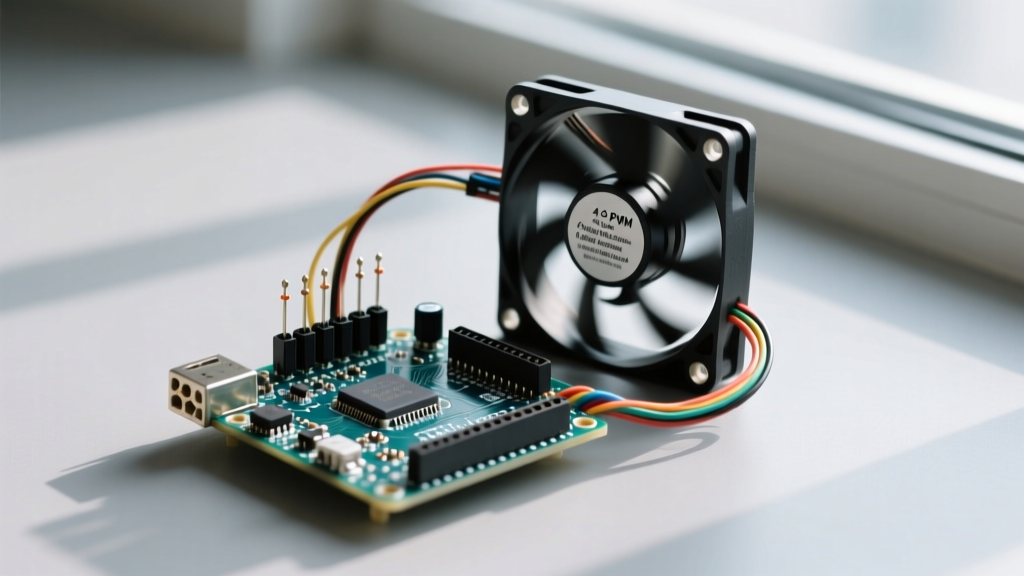

Thermal management in microcontroller projects is often treated as an afterthought, leading to noisy enclosures, premature component degradation, and erratic sensor readings. When integrating active cooling, the 4-pin PWM fan is the industry standard. However, makers frequently encounter a frustrating workflow bottleneck: fans that run at 100% speed, emit an audible high-pitched whine, or fail to report RPM data back to the MCU. These issues rarely stem from defective hardware; instead, they are the result of misaligned workflows that ignore the underlying Intel 4-Wire PWM specification.
Optimizing your development workflow for PWM fan control requires a systematic approach to hardware interfacing, non-blocking firmware generation, and automated calibration. By restructuring how you prototype and deploy cooling solutions, you can eliminate weeks of debugging and achieve silent, precision thermal control.
Decoding the 4-Wire Specification: Why Workflows Fail
The most common workflow killer is assuming a PWM fan operates like a standard DC motor where voltage dictates speed. According to the original Intel 4-Wire PWM Controlled Fans Specification, adopted by premium manufacturers like Noctua and Delta, the control pin requires a precise 25 kHz square wave (with a ±20% tolerance).
If your microcontroller outputs a signal outside this frequency band, the fan's internal logic board may default to a failsafe mode, running the motor at maximum RPM to prevent overheating. Furthermore, the specification dictates that the PWM control pin is an open-drain output inside the fan, requiring a pull-up resistor to 5V. Ignoring this electrical reality during the breadboarding phase guarantees signal degradation and logic threshold failures, especially when migrating from 5V AVR boards to 3.3V ESP32 or RP2040 ecosystems.
Hardware Workflow: Eliminating the 5V vs 12V Logic Trap
A streamlined hardware workflow begins with proper level shifting and signal conditioning. Many makers wire the MCU's PWM pin directly to the fan's PWM wire (Pin 4). While this might work on a 5V Arduino Uno, it introduces severe noise margins and risks back-feeding voltage into the MCU's GPIO pins.
The Open-Drain Pull-Up Solution
To optimize your hardware workflow and ensure cross-platform compatibility, implement a dedicated level-shifting stage. Because the fan's internal PWM circuit is open-drain, it pulls the signal line to ground when active, but relies on an external pull-up to register a 'HIGH' state.
- For 3.3V MCUs (ESP32/RP2040): Use an N-channel MOSFET (like the 2N7000) or a dedicated logic-level translator. Drive the gate with your 3.3V MCU pin, and pull the drain up to 5V via a 10kΩ resistor. This ensures the fan sees a crisp 5V logic HIGH while protecting your 3.3V silicon.
- For 24V Industrial Blowers: Never connect the tachometer or PWM lines directly to a 24V supply. Use an optocoupler (e.g., PC817) to isolate the 24V domain from your 5V/3.3V MCU logic, preventing catastrophic ground-loop failures.
Workflow Pro-Tip: Before connecting the fan, verify your PWM signal with a cheap 24MHz logic analyzer. Confirming the 5V amplitude and 25 kHz frequency on your PC screen takes two minutes and saves hours of hardware debugging.
Firmware Optimization: Ditching the Default analogWrite()
The default Arduino analogWrite() function operates at approximately 490 Hz. Driving a PWM fan at 490 Hz violates the 25 kHz specification and forces the fan's internal commutation circuitry to resonate, producing a highly annoying audible coil whine. Optimizing your firmware workflow means abandoning default functions in favor of hardware-specific timer configurations.
ESP32 LEDC vs. Arduino AVR Timer1
When working within the Espressif ecosystem, the ESP32 LEDC API provides a highly optimized workflow for generating precise high-frequency signals without blocking the main loop. By configuring the LEDC channel to 25,000 Hz with an 8-bit resolution, you achieve silent operation and granular speed control.
For legacy AVR boards (Arduino Uno/Mega), you must bypass analogWrite() and manipulate Timer1 registers directly. Setting the prescaler and waveform generation mode to Fast PWM with an ICR1 top value allows you to hit exactly 25 kHz on pins 9 and 10. Documenting these timer configurations in a centralized project wiki prevents team members from accidentally reverting to 490 Hz functions during future code merges.
The Calibration Jig: Automating Fan Curve Profiling
Manually guessing duty cycles to map a thermal curve is an inefficient use of engineering time. An optimized workflow incorporates an automated calibration jig that maps PWM duty cycles to actual RPM and airflow acoustics.
By utilizing the fan's Tachometer wire (Pin 3) and the Arduino attachInterrupt() function, you can build a serial-plotter-based profiling script. The tachometer outputs two pulses per revolution. By measuring the microseconds between falling edges using micros(), the MCU can calculate real-time RPM.
- Write a sweep function that increments the PWM duty cycle from 0% to 100% in 5% steps.
- Hold each step for 2 seconds to allow the rotor inertia to stabilize.
- Log the duty cycle, measured RPM, and MCU temperature to an SD card or serial terminal.
- Import the CSV data into Python or Excel to generate a precise, non-linear fan curve lookup table for your final production firmware.
This data-driven workflow eliminates the 'guess-and-check' method, ensuring your cooling system only uses the exact amount of power required to maintain thermal equilibrium, thereby extending fan lifespan and reducing acoustic noise.
Diagnostic Matrix: Rapid Troubleshooting
Even with an optimized workflow, environmental variables and component tolerances can introduce faults. Use the following diagnostic matrix to rapidly identify and resolve common PWM fan integration issues without resorting to trial-and-error part swapping.
| Symptom | Root Cause Analysis | Workflow Fix / Action |
|---|---|---|
| Fan runs at 100% regardless of code | PWM pin is floating, or frequency is below 1kHz (failsafe triggered). | Verify 25kHz frequency with logic analyzer; ensure pull-up resistor to 5V is present. |
| Loud, high-pitched audible whine | MCU is outputting default 490Hz or 980Hz PWM signal. | Reconfigure AVR Timer1 or ESP32 LEDC to strictly output 25,000 Hz. |
| RPM reading is erratic or zero | Tachometer line lacks a pull-up resistor, or interrupt is bouncing. | Add 10kΩ pull-up to 5V on Tach pin; implement software debouncing or hardware RC filter. |
| Fan stalls at low duty cycles | Insufficient starting voltage or static pressure too high for the fan model. | Implement a 'kickstart' routine in code: run at 100% for 500ms before dropping to target PWM. |
By treating PWM fan integration as a disciplined engineering workflow rather than a simple peripheral hookup, you elevate the reliability and professionalism of your MCU projects. Proper level shifting, strict adherence to the 25 kHz specification, and automated tachometer profiling transform a noisy, unreliable prototype into a robust, thermally optimized system.