
The Beginner's Trap: Why Your Screen Stays Black
There is a universal rite of passage for every electronics hobbyist: you wire up your first screen, upload the example sketch, and are met with a completely blank, glowing black screen. Interfacing a display with Arduino boards is supposed to be the most rewarding part of a DIY project, yet it is fraught with hidden hardware quirks, logic-level mismatches, and memory-hogging libraries.
This guide strips away the fluff and focuses on the exact technical realities of connecting the most popular beginner screen—the 0.96-inch I2C OLED—to an Arduino Uno or Nano. We will cover the specific silicon controllers hidden beneath the glass, the SRAM limitations that crash beginner code, and the exact troubleshooting steps to get pixels on the screen.
Choosing the Right Hardware: The SSD1306 Controller
When shopping for a beginner screen, you will encounter two main categories: the classic 16x2 character LCD (usually blue or green with a bulky potentiometer) and the 0.96-inch OLED. For modern projects, the 16x2 LCD is largely obsolete due to its high power draw, poor viewing angles, and massive physical footprint.
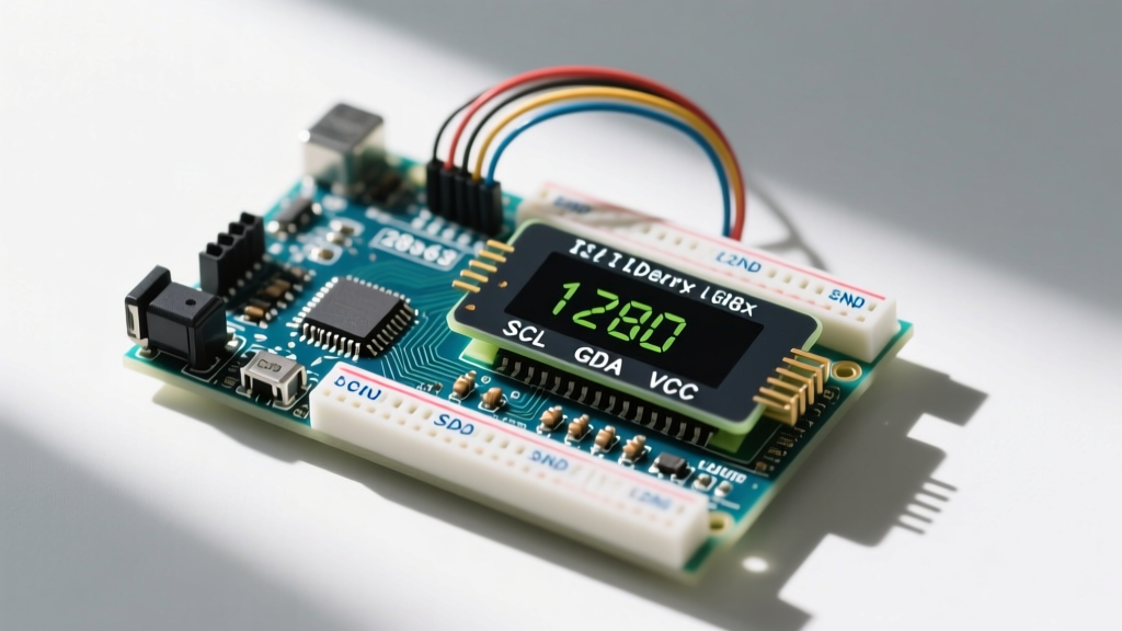
Instead, the 0.96-inch 128x64 OLED is the gold standard. However, you are not actually buying an 'OLED screen'; you are buying a breakout board built around a specific driver chip. In 95% of beginner modules sold on Amazon or AliExpress for roughly $4 to $7, this chip is the SSD1306 by Solomon Systech. Knowing the exact controller chip is critical because it dictates which software libraries you must use.
I2C vs. SPI: The Pin Count Reality
These OLEDs come in two communication flavors:
- SPI (7-pin): Faster refresh rates, but requires 7 wires (MOSI, CLK, DC, RST, CS, VCC, GND). This eats up valuable GPIO pins on an ATmega328P-based Arduino.
- I2C (4-pin): Slightly slower, but only requires 4 wires (VCC, GND, SCL, SDA). Because I2C is a shared bus, you can daisy-chain multiple sensors without using extra pins.
For 90% of beginner sensor dashboards, the 4-pin I2C version is the superior choice.
Exact Wiring Pinout for Arduino Uno and Nano
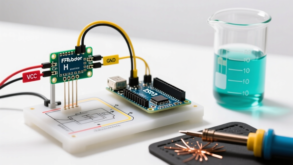
Wiring an I2C display with Arduino is straightforward, but the physical pin locations change depending on your specific board. Below is the definitive wiring matrix for the most common AVR boards.
| OLED Pin (I2C) | Arduino Uno / Nano | Arduino Mega 2560 | Function |
|---|---|---|---|
| GND | GND | GND | Common Ground Reference |
| VCC | 5V | 5V | Power Input (See warning below) |
| SCL | A5 | Pin 21 | I2C Clock Line |
| SDA | A4 | Pin 20 | I2C Data Line |
Critical E-E-A-T Warning: The 5V Logic Trap. Most cheap SSD1306 OLEDs have a 3.3V logic requirement for the SDA and SCL lines, even if the VCC pin accepts 5V via an onboard voltage regulator. The Arduino Uno outputs 5V logic. While the SSD1306 is somewhat 5V tolerant and will often work for months, this over-voltage condition will eventually degrade the I2C pins. For long-term reliability, use a bidirectional logic level shifter, or switch to a 3.3V Arduino board like the Nano 33 IoT.
Solving the I2C Address Mystery (0x3C vs 0x3D)
The number one reason a display with Arduino fails to initialize is an incorrect I2C address. The SSD1306 chip can operate on one of two hexadecimal addresses: 0x3C or 0x3D.
If you look at the back of the OLED PCB, you will see a tiny 0402 surface-mount resistor labeled SA0 (or sometimes R1/R3). This resistor pulls the address pin high or low. Most manufacturers default to 0x3C, but some batches ship configured to 0x3D. If your code hardcodes 0x3C and your board is 0x3D, the screen will remain permanently black.
Never guess the address. Always run the official Arduino I2C Scanner sketch first. Upload it to your board, open the Serial Monitor at 9600 baud, and let the Arduino poll the bus to tell you the exact address of your display.
Library Showdown: Adafruit vs. U8g2
Once wired, beginners typically rush to the Library Manager and install the first option they see. This is where memory disasters happen.
The Adafruit_SSD1306 Memory Problem
The Adafruit SSD1306 library is incredibly user-friendly, but it uses a full-framebuffer approach. To draw on a 128x64 screen, the library allocates a buffer in the Arduino's SRAM: 128 * 64 / 8 = 1024 bytes.
The ATmega328P chip on the Arduino Uno only has 2048 bytes of total SRAM. By simply initializing the display, you have just consumed 50% of your microcontroller's working memory. If you add a few strings, a Wi-Fi library, or sensor arrays, your Arduino will experience a stack collision and silently reboot in an endless loop.
The U8g2 Solution: Page Buffering
For serious projects, the U8g2 Library Wiki provides a vastly superior alternative. U8g2 supports 'page buffering'. Instead of holding the entire screen in RAM, it renders the display in 8-pixel high horizontal stripes (pages), sending them to the OLED sequentially. This reduces the SRAM footprint from 1024 bytes down to roughly 128 bytes, freeing up massive amounts of memory for your actual application logic.
While U8g2 has a slightly steeper learning curve regarding font selection and drawing commands, it is the only sustainable choice for complex Arduino sensor dashboards.
Real-World Troubleshooting: When the Display Fails
If you have verified the wiring and confirmed the I2C address, but the screen is still blank, you are likely facing one of these specific hardware failure modes:
- The ZIF Ribbon Cable Tear: The 0.96-inch OLED glass is connected to the PCB via a fragile Flexible Printed Circuit (FPC) ribbon. If you push the display into a breadboard by pressing on the glass, you will micro-fracture the traces inside the ribbon. Always press on the PCB edges.
- Missing I2C Pull-Up Resistors: The I2C protocol requires pull-up resistors on the SDA and SCL lines. Many cheap OLED clones omit these to save $0.02 in manufacturing. If your I2C scanner finds nothing, add two 4.7kΩ resistors between the SDA/SCL lines and the 3.3V VCC line.
- Dead Pixels and Burn-In: OLEDs are susceptible to burn-in if static elements (like a permanent border) are left on for hundreds of hours. Implement a pixel-shifting routine in your code that moves static text by 1 or 2 pixels every few minutes.
- Counterfeit SSD1306 Chips: Ultra-cheap modules sometimes use SH1106 clone controllers. The SH1106 is nearly identical but has a slightly different memory mapping (132x64 instead of 128x64). If your screen turns on but the image is shifted to the right with a black bar on the left, change your library initialization from SSD1306 to SH1106.
Final Thoughts on Peripheral Interfacing
Successfully integrating a display with Arduino is less about copying code and more about understanding the physical and memory constraints of your hardware. By choosing the I2C SSD1306, verifying addresses via scanner, and utilizing memory-efficient libraries like U8g2, you bypass the common beginner pitfalls and build a foundation for robust, professional-grade DIY electronics.