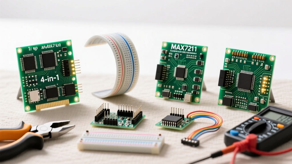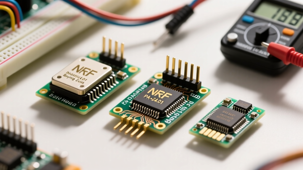

The nRF24L01 module remains the undisputed champion of low-cost, 2.4 GHz DIY wireless communication. Whether you are building a fleet of remote environmental sensors, a custom RC car, or a wireless MIDI controller, Nordic Semiconductor's iconic transceiver is likely at the top of your bill of materials. However, the market is flooded with dozens of physical variations, clone silicon, and misleading range claims. Buying the wrong variant—or failing to support it with the right power delivery—will result in dropped packets and endless debugging sessions.
This comprehensive buying guide cuts through the marketplace noise. We will break down the exact hardware variants available in 2026, expose the infamous power starvation issue, and help you identify counterfeit silicon so your next RF project actually works on the first upload.
The Core Silicon: nRF24L01 vs. nRF24L01+
Before evaluating the breakout boards, you must understand the silicon underneath. The original nRF24L01 was released in the mid-2000s, but it was quickly superseded by the nRF24L01+ (often denoted with a plus sign). According to Nordic Semiconductor's official documentation, the '+' revision introduced a crucial new data rate of 250 kbps, which dramatically increases receiver sensitivity and maximum range. It also reduced the peak RX current consumption. When shopping, ensure the product listing explicitly states 'nRF24L01+'. If a vendor is still selling the non-plus version, walk away; it is obsolete and incompatible with modern library optimizations.
Hardware Variant Matrix: Which Board Do You Need?
The raw nRF24L01+ chip is a 4x4mm QFN package that requires a precise RF matching network and a 2.4 GHz antenna. To save you from high-frequency PCB layout nightmares, manufacturers sell the chip on pre-routed breakout boards. Here is how the primary variants stack up against each other.
| Module Variant | Antenna Type | Max TX Power | Typical LOS Range | Peak TX Current |
|---|---|---|---|---|
| Base (DIP) | PCB Trace | 0 dBm | ~30 meters | ~11.3 mA |
| SMD (Mini) | PCB Trace | 0 dBm | ~20 meters | ~11.3 mA |
| PA+LNA (High Power) | SMA (External) | +20 dBm | ~1,000+ meters | ~115 - 130 mA |
| DIP + External Antenna | SMA (External) | 0 dBm | ~100 meters | ~11.3 mA |
The Verdict: For indoor sensor networks where nodes are separated by a few drywall partitions, the Base DIP module is perfect. For long-range outdoor telemetry (e.g., weather stations or agricultural monitoring), you must invest in the PA+LNA (Power Amplifier + Low Noise Amplifier) variants. The SMD 'mini' versions are best reserved for space-constrained wearable prototypes, though their range suffers heavily due to the compromised ground plane.
The 3.3V Power Starvation Crisis
The single most common reason an nRF24L01 module fails to initialize or drops packets during transmission is power starvation. The module operates strictly at 3.3V. While the logic pins on the nRF24L01+ are largely 5V-tolerant on inputs, the VCC rail is not.
When the module transmits at maximum power, it draws instantaneous current spikes of up to 115 mA. Most standard Arduino Nano or Uno clones utilize a basic linear regulator for their 3.3V pin that maxes out at 50 mA (or less). When the nRF24L01 demands 115 mA, the local voltage sags below the chip's brownout threshold (typically 1.9V), causing the internal state machine to crash or the SPI bus to desync.
Pro-Tip from the Bench: Never power a high-gain PA+LNA module directly from a microcontroller's 3.3V pin. Use a dedicated nRF24L01 Adapter Board featuring an AMS1117-3.3 or HT7333 LDO voltage regulator, and feed it from the microcontroller's 5V rail.
If you are using the standard low-power DIP module without an adapter, you must solder a 10µF to 47µF electrolytic or tantalum bypass capacitor directly across the VCC and GND pins on the module header. This capacitor acts as a local energy reservoir, supplying the instantaneous 115mA burst that the microcontroller's regulator cannot provide fast enough. The SparkFun Hookup Guide heavily emphasizes this capacitor trick for reliable deployments.
Navigating the Clone Chip Minefield (SI24R1)
Because the original Nordic patents have expired and the silicon design is well-documented, the market is saturated with clone chips. The most prevalent is the SI24R1 manufactured by Nanjing Zhongke Microelectronics. On the surface, the SI24R1 mimics the nRF24L01+ perfectly, but it features a few critical deviations:
- Higher TX Power: The SI24R1 can push up to +7 dBm (compared to the genuine chip's 0 dBm) without an external PA.
- Worse RX Sensitivity: The receiver noise floor is notably higher, meaning asymmetric links where the clone can 'shout' but cannot 'hear' the genuine node are common.
- Register Defaults: The SI24R1 often ships with different default values in the SETUP_RETR register, leading to immediate auto-acknowledgment failures if your code relies on the nRF24L01+ datasheet defaults.
How do you handle this? First, inspect the chip markings. Genuine Nordic chips have crisp, laser-etched logos and batch codes. SI24R1 chips often have slightly blurred printing or a distinct circular dimple in a different location. Second, use the widely adopted TMRh20 RF24 Library for Arduino/C++, which includes specific workarounds and initialization routines designed to force the SI24R1 into a compatible state.
Antenna Topologies and Real-World Range
Marketing materials on auction sites frequently claim '1000 meter range' for standard modules. This is measured in a vacuum, with perfect line-of-sight, at the lowest data rate (250 kbps), and with zero 2.4 GHz Wi-Fi interference. In a real-world suburban environment, expect the following:
Optimizing for Penetration vs. Speed
The nRF24L01+ supports three air data rates: 2 Mbps, 1 Mbps, and 250 kbps. If you are building a wireless keyboard or a low-latency drone control link, you need 2 Mbps or 1 Mbps. However, range will be limited to roughly 15-30 meters indoors. If you are sending small telemetry packets (like soil moisture or temperature) once per minute, configure your library to use 250 kbps. This drops the noise floor, effectively adding 6 to 9 dB of link budget, which can double or triple your physical range through obstacles.
SPI Wiring and Logic Level Translation
The nRF24L01 module communicates via SPI (Serial Peripheral Interface). It requires six connections: VCC, GND, CE (Chip Enable), CSN (Chip Select Not), SCK (Clock), MOSI (Master Out Slave In), and MISO (Master In Slave Out).
While the SPI inputs on the nRF24L01+ (CE, CSN, SCK, MOSI) are generally tolerant of 5V logic from an Arduino Mega or Uno, the output pin (MISO) will only ever output 3.3V. Most 5V AVR microcontrollers will reliably read 3.3V as a logic HIGH, but it sits dangerously close to the undefined threshold region. If you are using an ESP32 or a modern 3.3V ARM Cortex board (like the Raspberry Pi Pico), you can wire them directly. If you are using a strict 5V system and experiencing corrupted SPI reads, insert a bidirectional logic level shifter or a simple CD4050 non-inverting buffer on the MISO line.
The Ultimate Shopping Cart Checklist
Before you check out on your favorite electronics distributor, ensure your cart includes the following to guarantee a frictionless build:
- The Modules: 2x nRF24L01+ PA+LNA (for long range) OR 2x Base DIP (for indoor).
- Adapter Boards: 2x nRF24L01 Socket Adapters with onboard 3.3V LDOs (eliminates the need for messy jumper wires and breadboard contact resistance).
- Capacitors: A pack of 10µF or 47µF electrolytic capacitors (if not using adapter boards).
- Antennas: If buying PA+LNA modules, ensure they include the SMA duck antennas. Upgrading to a high-gain directional Yagi antenna later can push your range well past 1.5 kilometers.
- Wiring: Pre-crimped Dupont wires. The standard 2x4 header on the module is notoriously loose on cheap breadboards; secure wiring is mandatory for high-frequency SPI stability.
By understanding the silicon revisions, respecting the strict 3.3V power requirements, and selecting the correct antenna topology for your environment, the nRF24L01 module transitions from a frustrating breadboard paperweight into a highly reliable, ultra-low-cost wireless backbone for your electronics projects.