
Building a prototype on a solderless breadboard is a fundamental rite of passage for electrical engineers and DIY hobbyists. Yet, one of the most common sources of immense frustration is a circuit that simply refuses to work, despite a flawless schematic. The culprit is rarely the silicon; it is almost always the physical layer. Understanding exactly how a breadboard is connected internally is the first step toward mastering prototype troubleshooting.
When you push a component lead into a plastic hole, you are blindly trusting a hidden mechanical contact. Over time, these contacts degrade, splay, or oxidize, leading to phantom open circuits, intermittent voltage drops, and high-frequency signal degradation. This troubleshooting guide will dissect the internal matrix of a standard 830-tie-point breadboard, explain the physics of the contacts, and provide a rigorous multimeter workflow to diagnose and fix connection failures.
The Hidden Matrix: How a Breadboard is Connected Internally
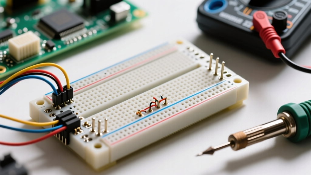
To troubleshoot a breadboard, you must first visualize the subterranean copper and phosphor bronze pathways beneath the ABS plastic faceplate. A standard full-size breadboard is divided into two primary connection zones: the terminal strips and the power rails (bus bars).
Terminal Strips and the Center Ravine
The main working area consists of columns labeled a through j. Beneath the surface, how the breadboard is connected in this zone relies on vertical metal clips. Holes a-e share a single continuous metal clip, and holes f-j share another. Crucially, the center ravine (the ditch running horizontally down the middle) breaks this connection. This ravine is precisely 0.3 inches (7.62mm) wide, designed to straddle standard Dual In-line Package (DIP) integrated circuits without shorting the opposing pins.
If you insert a jumper wire into 1a and another into 1e, they are electrically connected. If you insert one into 1e and another into 1f, they are completely isolated. A common beginner mistake is straddling a single component across the ravine incorrectly, or assuming the entire row from a to j is one continuous node.
Power Rails (Bus Bars)
Running along the top and bottom edges are the power rails, typically marked with red (+) and blue (-) lines. Unlike the terminal strips, how the breadboard is connected here is horizontal. The entire length of the rail shares a single, continuous metal strip. However, on many half-size or older full-size boards, the horizontal bus bar is split in the exact middle. If your microcontroller is powered from the left side of the board and your motor driver is on the right, they will not share a common ground unless you explicitly bridge the center gap with a jumper wire.
The Physics of the Contact: Why Connections Fail
Inside each hole sits a tiny, stamped metal clip, usually made of phosphor bronze or nickel-silver, often plated with a micro-layer of gold or tin to prevent oxidation. When you insert a wire, the clip acts as a cantilever spring, applying lateral pressure against the wire to maintain electrical continuity.
According to SparkFun's comprehensive breadboard guide, these clips are engineered for a very specific wire gauge. The ideal wire is 22 AWG to 26 AWG solid core. Understanding this mechanical limitation is critical for troubleshooting:
- Using Stranded Wire: The individual strands splay out, bending the clip outward. Once you remove the stranded wire, the clip remains permanently deformed, resulting in an open circuit for any subsequent 24 AWG solid wires you insert.
- Using Thick Wire (20 AWG or larger): Forcing thick component leads (like heavy-duty potentiometers or terminal blocks) stretches the spring past its yield point. The clip loses its clamping force entirely.
- Using Thin Wire (30 AWG wire-wrap): The wire is too thin for the spring to grip tightly, leading to high contact resistance and susceptibility to vibration-induced open circuits.
Expert Troubleshooting Tip: Never use stranded wire directly in a breadboard. If you must use stranded wire for flexibility, crimp a solid ferrule pin onto the end before insertion, or solder a short piece of 22 AWG solid header wire to act as a rigid adapter.
Troubleshooting Matrix: Diagnosing Connection Failures
When a prototype fails, use this diagnostic table to isolate the physical connection fault before rewriting your code or replacing your ICs.
| Failure Mode | Typical Symptom | Multimeter Diagnostic | Resolution Strategy |
|---|---|---|---|
| Splayed Clip (Open Circuit) | IC receives no power; floating logic pins read random noise. | Continuity test between component lead and adjacent test point reads 'OL' (Open Loop). | Move the component one row down to a fresh, un-deformed clip. Discard the board if widespread. |
| Oxidized Contact | Analog sensor readings drift; microcontroller browns out under load. | Resistance mode (200Ω) reads 5Ω to 50Ω instead of <0.5Ω. | Unplug and re-insert the wire 4-5 times to scrape off the oxidation layer via mechanical friction. |
| Split Rail Gap | Half the circuit is dead; I2C bus fails to pull high. | Voltage check at the far end of the blue rail reads 0V despite 5V at the source. | Install a dedicated jumper wire bridging the physical gap in the center of the horizontal bus bar. |
| Stray Shorting | Power supply enters over-current protection; ICs overheat. | Resistance between VCC and GND rails reads near 0Ω with power disconnected. | Inspect for clipped component leads fallen into the plastic gaps, or stray wire strands bridging the ravine. |
Advanced Multimeter Diagnostics: Beyond the Beeper
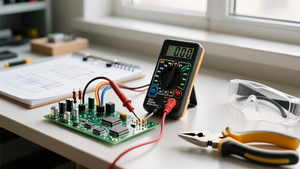
The most dangerous tool in a troubleshooter's arsenal is the multimeter's continuity beeper. Most standard digital multimeters (like the popular Fluke 115 or cheaper UNI-T models) will trigger the continuity beep if the resistance is anywhere below 30Ω to 50Ω.
However, a breadboard connection should ideally have a contact resistance of less than 100 milliohms (0.1Ω). If a degraded breadboard clip is introducing 15Ω of resistance, your multimeter will happily beep, telling you the connection is 'good.' But if your servo motor draws 2 Amps through that 15Ω connection, Ohm's Law (V = IR) dictates a massive 30-Volt drop, instantly starving the motor and resetting your logic circuits.
The Voltage Drop Test Under Load
To truly verify how the breadboard is connected under real-world conditions, you must perform a dynamic voltage drop test.
- Power your circuit and put it into a high-load state (e.g., turn on all LEDs, spin the motors, or trigger the Wi-Fi radio on an ESP32).
- Set your multimeter to DC Voltage (20V range).
- Place the black probe directly on the power supply's output terminal.
- Place the red probe on the VCC pin of the microcontroller or load.
If your power supply outputs 5.00V, but your multimeter reads 4.20V at the IC, you have a 0.8V drop occurring entirely within the breadboard's internal bus bars and clips. This confirms severe contact degradation or an overloaded bus bar. The fix is to bypass the breadboard's power rails entirely and solder heavy-gauge silicone wires directly from the power supply to the high-current modules.
Parasitic Capacitance and High-Frequency Limitations
For DC and low-frequency analog circuits, the breadboard is a reliable tool. But if you are troubleshooting RF circuits, high-speed switching regulators, or fast op-amp oscillators, you must understand the parasitic elements of the internal matrix.
As detailed in various prototyping guides by Adafruit, adjacent rows of metal clips sitting parallel to one another act as tiny capacitors. The stray capacitance between two adjacent rows on a standard breadboard is typically between 2pF and 5pF. While this sounds negligible, at 100 MHz, a 5pF capacitor has an impedance of roughly 318Ω. This means high-frequency signals will 'bleed' or cross-talk into adjacent rows, causing ghost signals, ringing, and unstable oscillator frequencies.
Troubleshooting High-Frequency Bugs:
If your high-speed digital signals are exhibiting severe ringing or overshoot on your oscilloscope, the breadboard's parasitic inductance and capacitance are the culprits. To mitigate this without moving to a custom PCB:
- Keep high-speed signal traces as short as physically possible.
- Do not route sensitive analog signals parallel to digital clock lines on adjacent rows.
- Use a ground plane technique by inserting a continuous wire mesh or dedicating every other row to ground to act as a shielding barrier.
When to Retire Your Breadboard
Breadboards are consumable tools, not permanent fixtures. A high-quality board from brands like SparkFun or Bus Pirate features gold-flashed phosphor bronze clips that can withstand thousands of insertions. Cheap, no-name clones often use un-plated stamped steel that will oxidize and fail within a few months of standard humidity exposure.
If you find yourself constantly wiggling wires to maintain a connection, or if a 22 AWG solid wire slides into a hole with zero tactile friction and resistance, the mechanical spring has failed. It is time to recycle the board and transition your finalized schematic to a perfboard or a manufactured PCB.
Conclusion
Mastering how a breadboard is connected transforms you from a frustrated hobbyist into a systematic troubleshooter. By respecting the mechanical limits of the internal clips, utilizing proper wire gauges, and relying on dynamic voltage-drop testing rather than simple continuity beepers, you can eliminate 90% of the physical errors that plague early-stage prototypes. Treat your breadboard matrix with precision, and your circuits will reliably come to life.