
Why the MAX7219 Remains the Maker Standard
When it comes to scrolling text, retro pixel art, or real-time telemetry dashboards, the MAX7219 LED matrix ecosystem remains unbeatable for its cost-to-effort ratio. Originally designed by Maxim Integrated (now part of Analog Devices), the MAX7219 is a serial input/output common-cathode display driver. Unlike raw shift registers like the 74HC595, the MAX7219 handles the intensive multiplexing and refresh rates in dedicated hardware. This frees your microcontroller's CPU to handle Wi-Fi stacks, sensor polling, or complex animation math without suffering from display flicker.
In this 2026 equipment roundup, we are moving past the basic 'hello world' tutorials. We will dissect the specific MAX7219 LED matrix kits available on the market today, evaluate their PCB build quality, and dive deep into the real-world electrical failure modes that plague beginners—such as SPI signal degradation, UVLO brownouts, and logic-level mismatches.
The Anatomy of a MAX7219 Module: Beyond the LEDs
Before buying a kit, you must understand the RSET (or ISET) resistor located near the IC. The MAX7219 uses this single resistor to set the peak current for all 64 LEDs in the matrix. Most generic, budget-friendly modules ship with a 10kΩ surface-mount resistor. According to the Analog Devices datasheet, a 10kΩ resistor limits the segment current to roughly 20mA. Because the chip multiplexes the 8 rows at a 1/8 duty cycle, the average current per LED is much lower, keeping the module cool.
If you are building an outdoor clock or a high-ambient-light dashboard, you might be tempted to swap this resistor for a 4.7kΩ version to double the brightness. However, doing so on a cheap 4-in-1 module will push the total peak current draw past 1.5 Amps, which will instantly melt the thin 10-mil copper traces on the VCC rail of budget PCBs. Always match your kit's PCB trace width to your desired brightness.
2026 Kit Roundup: Top MAX7219 LED Matrix Modules
1. The Standard 4-in-1 FC-112 (8x32 Rigid)
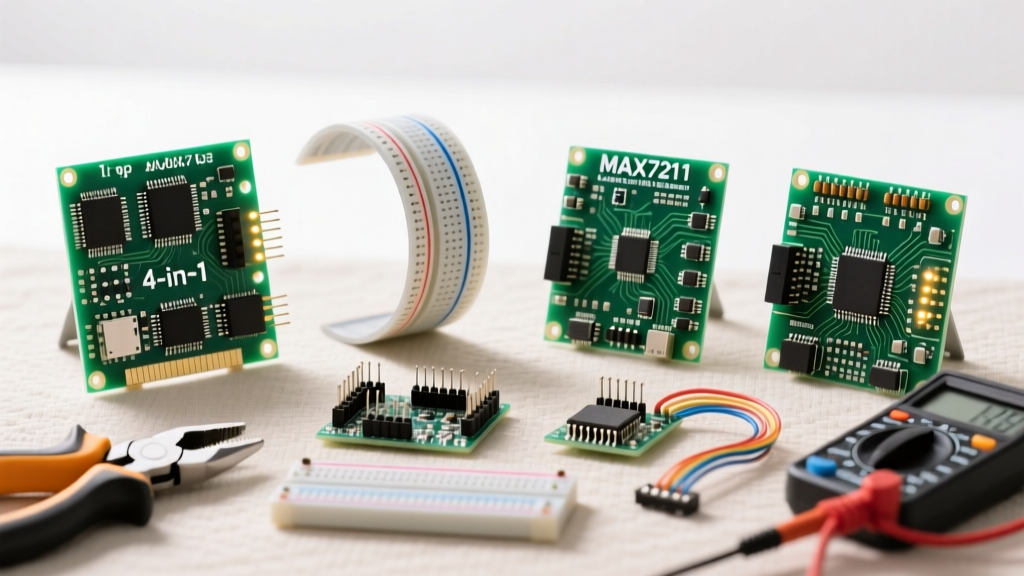
The FC-112 is the undisputed workhorse of the maker community. It features four 8x8 matrices mounted on a single, rigid FR4 PCB. The primary advantage is the integrated SPI pass-through; the DIN, CLK, CS, VCC, and GND pins are routed straight through the board, allowing you to daisy-chain multiple units simply by plugging them end-to-end.
The Catch: The rigid PCB is actually a weakness in high-vibration environments or if you attempt to force it into a slightly curved 3D-printed enclosure. The FR4 board will flex, causing the surface-mount MAX7219 ICs to crack their solder joints. If you use the FC-112, ensure your enclosure provides rigid, flat support across the entire 130mm length.
2. Flexible FPC 8x32 LED Matrix Panels
For wearable tech, curved automotive dash replicas, or cylindrical pillar displays, the Flexible Printed Circuit (FPC) MAX7219 kits are the premium choice. These modules use a thin polyimide substrate instead of fiberglass FR4. The LEDs and ICs are surface-mounted directly onto the flex PCB.
The Catch: While they can bend to a radius of about 50mm, they are incredibly fragile during the soldering and assembly process. Furthermore, because they lack a rigid backing, you must design custom 3D-printed sleds or use double-sided thermal tape to mount them, otherwise the physical pressure of the jumper wires will tear the solder pads right off the flex board.
3. Generic Single 8x8 Modules (The Daisy-Chain Approach)
Sold in packs of 5 or 10, these individual 8x8 modules give you ultimate geometric freedom. You can arrange them in a cross, a circle, or a staggered 2x16 layout. They are ideal for custom art installations where standard rectangular grids look too 'commercial'.
The Catch: Wiring is a nightmare. You will need to solder dozens of jumper wires between the DOUT of one module to the DIN of the next. This creates a massive amount of parasitic capacitance on the SPI bus, which we will discuss in the troubleshooting section below.
Comparative Specifications & Pricing Table
| Module Type | Resolution | Peak Current (All On) | Avg Price (USD) | Best Use Case |
|---|---|---|---|---|
| FC-112 Rigid 4-in-1 | 8x32 | ~1.2A | $5.00 - $8.00 | Desktop clocks, info tickers |
| FPC Flexible 4-in-1 | 8x32 | ~1.0A | $9.00 - $13.00 | Curved dashboards, wearables |
| Single 8x8 Generic | 8x8 (Scalable) | ~330mA per unit | $1.50 - $2.50 | Custom geometric art, props |
| ESP32 + MAX7219 Combo | 8x32 + Wi-Fi | ~1.5A (Total) | $14.00 - $18.00 | IoT dashboards, MQTT nodes |
Real-World Failure Modes & Troubleshooting
Buying the kit is only 20% of the battle. The remaining 80% is dealing with the electrical realities of driving hundreds of multiplexed LEDs. Here are the most common failure modes we see in the field, and how to engineer around them.
1. The UVLO Brownout Trap
When you command a 4-chip MAX7219 module to turn all 256 LEDs on at 100% brightness, it will attempt to draw roughly 1.2 to 1.5 Amps. If you are powering this directly from the 5V pin of an Arduino Uno or the USB VBUS of an ESP32, you will hit a wall. Standard USB ports limit at 500mA, and Arduino onboard linear regulators will overheat and shut down at 800mA.
When the voltage sags below 4.0V, the MAX7219 triggers its internal Undervoltage Lockout (UVLO), resetting the chip. This manifests as random screen blanking or garbage pixels. The Fix: Never power a matrix chain from the microcontroller's 5V pin. Use a dedicated 5V 3A buck converter (like an LM2596 module), tie the grounds together, and inject power directly into the VCC/GND header of the display.
2. SPI Signal Degradation and Ghosting
The MAX7219 communicates via a 10MHz SPI bus. When you daisy-chain six or more modules together, the long copper traces and cheap Dupont jumper wires act as a massive capacitor. This parasitic capacitance rounds off the sharp square-wave edges of your CLK (clock) signal. By the time the signal reaches the 6th module, the microcontroller's logic '1' might look like a '0', resulting in ghosting, shifted pixels, or flickering.
Pro-Tip: If you must run long chains, keep your SPI wires under 30cm. If you need to push the signal further, use a 74HCT14 hex inverter or a dedicated SPI buffer IC to clean up the clock edges before they enter the first MAX7219 DIN pin.
3. The 3.3V vs 5V Logic Level Mismatch
Modern microcontrollers like the ESP32, Raspberry Pi Pico, and RP2040 operate at 3.3V logic. However, the MAX7219 datasheet specifies a minimum High-Level Input Voltage ($V_{IH}$) of 3.5V when running on a 5V supply. Technically, feeding a 3.3V logic signal into a 5V MAX7219 is out of spec.
While it 'usually' works in a quiet room due to silicon tolerances, turning on a nearby relay, motor, or Wi-Fi antenna can introduce enough noise to cause the SPI bus to misinterpret bits. For a bulletproof commercial or permanent installation, always use a bidirectional logic level shifter (like a BSS138 MOSFET-based module) between your 3.3V MCU and the 5V display.
Software Stack: MD_Parola vs. LEDMatrix
Hardware is only half the equation. To drive these matrices efficiently, you need robust software. The gold standard in the Arduino ecosystem is the MD_Parola library by MajicDesigns, paired with its underlying MD_MAX72XX hardware abstraction layer.
MD_Parola handles the heavy lifting of hardware SPI communication, allowing you to define zones, scroll text with various entry/exit effects, and manage double-height characters. For those using Raspberry Pi or Linux-based SBCs, the luma.led_matrix Python library is the equivalent standard, offering Pillow (PIL) integration so you can render standard TrueType fonts directly to the 8x32 grid without manually mapping bitmaps.
Final Verdict & Build Recommendations
If you are building a standard desktop weather station or a simple scrolling crypto-ticker, the FC-112 Rigid 4-in-1 remains the most cost-effective and beginner-friendly MAX7219 LED matrix kit available in 2026. However, if your project involves complex geometries, wearable integration, or curved surfaces, invest the extra few dollars in the FPC Flexible panels.
Regardless of the kit you choose, respect the physics of the SPI bus and the current limits of the PCB traces. Inject external power, buffer your clock lines for long chains, and use proper logic level translation. By treating these cheap modules with professional electrical engineering practices, you can build displays that run flawlessly for years.