
The Intersection of Physics and the National Electrical Code
When designing or troubleshooting an electrical system, understanding the fundamental relationship between the conductor and insulator of electricity is not just a matter of basic physics—it is a strict code requirement. The National Electrical Code (NEC), specifically Article 310, governs how these materials must be paired, sized, and protected to prevent catastrophic thermal failures. While a physicist defines a conductor by its free electron density and an insulator by its band gap, an electrical inspector defines them by their ampacity, temperature ratings, and dielectric strength under real-world stress.
Choosing the correct conductor and insulator of electricity requires navigating a complex matrix of environmental factors, terminal temperature limitations, and raceway fill derations. This guide bridges the gap between material science and NEC compliance, providing electricians, engineers, and DIY enthusiasts with the exact frameworks needed to pass inspection and ensure long-term system reliability.
Material Science: Copper, Aluminum, and the NEC
The NEC recognizes both copper and aluminum as primary conductive materials, but their physical properties dictate vastly different installation rules. Copper remains the gold standard for branch circuits due to its high conductivity (approximately 100% IACS) and resistance to galvanic corrosion. However, aluminum is frequently used for service entrance conductors and heavy feeders due to its cost-to-weight ratio.
From a code perspective, you cannot simply use any aluminum wire. According to NEC 310.106, aluminum conductors must be made from an AA-8000 series electrical grade aluminum alloy. This specific alloy was developed in the 1970s to solve the creep and thermal expansion issues that caused widespread residential fires when older, pure aluminum (AA-1350) was used under copper-rated terminals. The insulator must also be chosen carefully; aluminum expands and contracts more than copper under thermal load, which can cause rigid, thin insulations to micro-crack over time, exposing the conductor to moisture and arc faults.
Decoding Insulation Types: NEC Table 310.104(A)
The insulator of electricity serves two primary purposes: containing the electromagnetic field (dielectric isolation) and protecting the conductor from environmental degradation (thermal, chemical, and UV resistance). The NEC categorizes these insulations by their maximum operating temperatures and approved environments.
| Insulation Type | Material Base | Max Temperature | Environment | Primary Application |
|---|---|---|---|---|
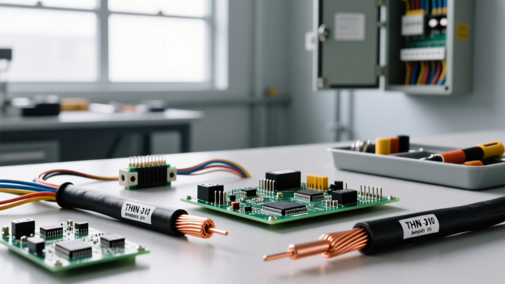
| THHN / THWN-2 | PVC with Nylon Jacket | 90°C (Dry) / 75°C (Wet) | Dry and Damp (Wet if THWN-2) | Standard commercial raceways, indoor panels |
| XHHW-2 | XLPE (Cross-Linked Polyethylene) | 90°C (Dry and Wet) | Dry, Damp, and Wet | Underground conduit, outdoor wet locations, harsh environments |
| USE-2 | XLPE or EPR | 75°C | Underground, Wet, Sunlight Resistant | Direct burial service laterals, outdoor feeders |
| MTW | PVC | 60°C (Wet) / 90°C (Dry) | Machine Tool Wiring | Industrial control panels, flexible machinery wiring |
The Superiority of XLPE Over PVC in Modern Installations
While THHN (Polyvinyl Chloride with a nylon skin) is the most common wire found on hardware store shelves, XHHW-2 (Cross-Linked Polyethylene) is vastly superior for demanding applications. XLPE is created by irradiating or chemically treating polyethylene, creating a 3D molecular matrix that does not melt under extreme heat. If a THHN conductor experiences a short-circuit overload, the PVC insulation will melt and slump at approximately 105°C, potentially causing a phase-to-phase fault. XHHW-2 maintains its structural integrity and dielectric strength even during short-circuit events exceeding 250°C, making it the preferred insulator of electricity for critical infrastructure.
The 110.14(C) Trap: Terminal Temperature Limitations
The most common code violation regarding the conductor and insulator of electricity involves ampacity sizing. Many electricians assume that because THHN is rated for 90°C, they can use the 90°C column in NEC Table 310.15(B)(16) to size the breaker and wire. This is fundamentally incorrect for most terminations.
NEC 110.14(C) dictates that the ampacity of a conductor must be based on the lowest temperature rating of any connected termination, device, or conductor in the circuit. Most standard circuit breakers, lugs, and receptacles under 100 amps are only tested and rated for 60°C or 75°C.
The Golden Rule of Ampacity: You may use the 90°C column of a conductor's insulation rating only for derating purposes (such as adjusting for high ambient temperatures or bundling more than three current-carrying conductors in a raceway). The final, derated ampacity must still be equal to or greater than the load, but the base starting ampacity for overcurrent protection sizing must respect the terminal's 60°C or 75°C limit.
For example, a 4 AWG copper THHN wire has a 90°C ampacity of 95A. However, if it is terminated on a standard 75°C rated breaker lug, the wire's maximum allowable ampacity for overcurrent protection is capped at 85A (its 75°C rating). The 90°C insulation acts merely as a thermal buffer for derating calculations, not a free pass to push more current.
Real-World Failure Modes: When the Insulator Fails
Understanding how the insulator of electricity degrades is critical for predictive maintenance and forensic troubleshooting. Insulation failure rarely happens instantly; it is a progressive deterioration accelerated by specific environmental stressors.
- Thermal Aging (Arrhenius Equation): For every 10°C increase in operating temperature above the insulation's rated limit, the lifespan of the polymer insulator is effectively cut in half. A THHN wire continuously operating at 105°C in a poorly ventilated conduit will become brittle and crack within a few years.
- Dielectric Breakdown: In high-voltage or transient-heavy environments (like VFD motor leads), voltage spikes can exceed the insulator's dielectric strength (measured in kV/mm). This causes microscopic tracking within the XLPE or PVC, eventually leading to a complete short circuit.
- UV and Ozone Degradation: Standard THHN is not sunlight resistant. If exposed to UV rays in an outdoor cable tray, the PVC jacket will chalk, crack, and expose the bare conductor within months. In these scenarios, USE-2 or XHHW-2 with specific UV inhibitors must be specified.
- Hydrolysis in Wet Locations: Nylon jackets (like the outer layer of THHN) are hygroscopic, meaning they absorb water over time when submerged or in continuously wet conduits. This causes the nylon to degrade and the underlying PVC to leach plasticizers, resulting in ground faults.
Sizing, Derating, and the Physics of Bundling
When multiple conductors are pulled into a single raceway, the heat generated by the I²R (I-squared-R) losses of each conductor cannot dissipate efficiently. The NEC requires ampacity derating based on the number of current-carrying conductors (NEC Table 310.15(B)(3)(a)).
If you pull four to six current-carrying conductors in a single conduit, you must multiply the conductor's base ampacity by 80%. If you pull seven to nine, the derating factor drops to 70%. This is where the 90°C rating of modern insulators becomes invaluable. By starting your derating math from the 90°C column, you can often maintain the required ampacity without having to increase the physical gauge of the copper or aluminum, saving significant material costs and conduit fill space.
For deeper research into dielectric material sciences and insulation testing standards, the IEEE Dielectrics and Electrical Insulation Society provides extensive peer-reviewed data on polymer degradation and partial discharge testing in solid insulators.
Field Verification Checklist for Inspectors and Electricians
Before energizing a new feeder or branch circuit, verify the conductor and insulator pairing against this NEC compliance checklist:
- Verify the Printing: Inspect the wire jacket to ensure it explicitly lists the NEC type (e.g., XHHW-2), AWG size, and voltage rating (typically 600V). Unmarked wire is an automatic code violation (NEC 310.120).
- Check the Environment Match: Confirm that wet-location conductors (THWN-2, XHHW-2, USE-2) are used in outdoor conduits, underground vaults, or concrete-encased ducts where condensation is guaranteed.
- Confirm Terminal Torque: Insulation damage often occurs at the termination point due to loose connections causing localized arcing and heat. Use a calibrated torque screwdriver or wrench to meet the manufacturer's terminal torque specifications (NEC 110.14(D)).
- Validate Derating Math: If more than three current-carrying conductors share a raceway, document the derating calculation on the as-built drawings to prove the final ampacity still exceeds the overcurrent protective device rating.
- Inspect for Jacket Damage: Check the ends of pulled wires. If the nylon skin of THHN was stripped back too far by aggressive pulling lubricants or sharp conduit burrs, the bare PVC is vulnerable to moisture ingress.
Ultimately, the safe transmission of electrical power relies on respecting the physical limits of both the conductor and insulator of electricity. By aligning material science with the rigorous demands of the National Electrical Code, professionals can design systems that are not only legally compliant but resilient against the unforgiving realities of thermal and electrical stress.
For the most current code cycles and safety bulletins, always refer to the official NFPA National Electrical Code documentation and consult your local Authority Having Jurisdiction (AHJ) regarding regional amendments.