
Defining the Boundary: What Is an Insulator and a Conductor?
At the most fundamental level of electrical theory, the flow of energy relies on a strict physical boundary. When professionals and DIYers ask, "what is an insulator and a conductor," they are usually looking for a basic physics definition. However, from an electrical safety perspective, understanding these materials requires looking beyond atomic structures and examining how they behave under thermal stress, mechanical duress, and environmental degradation. Misunderstanding the operational limits of either material is the root cause of catastrophic arc flashes, electrical fires, and fatal shocks.
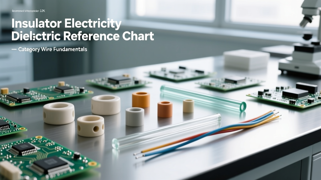
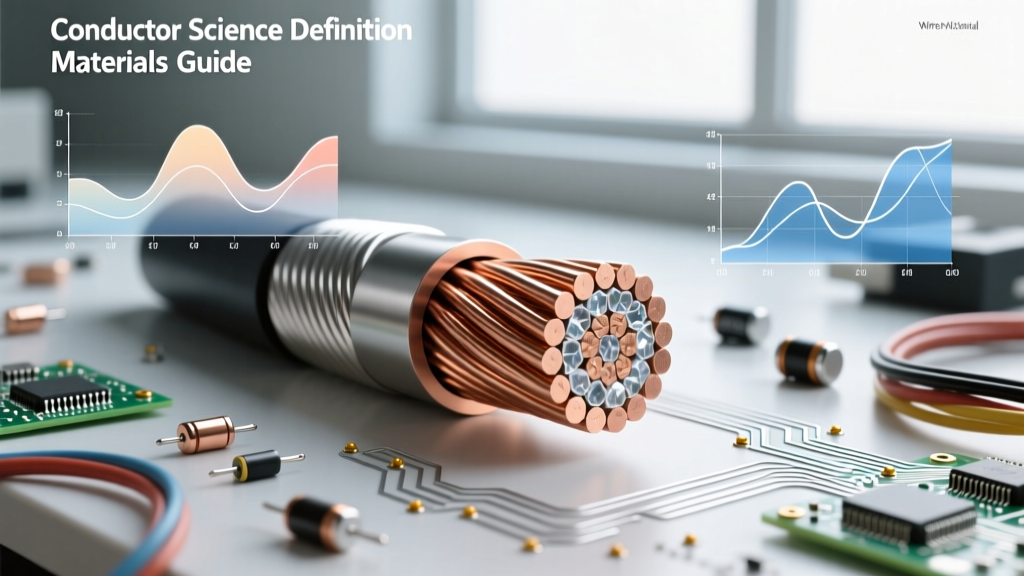
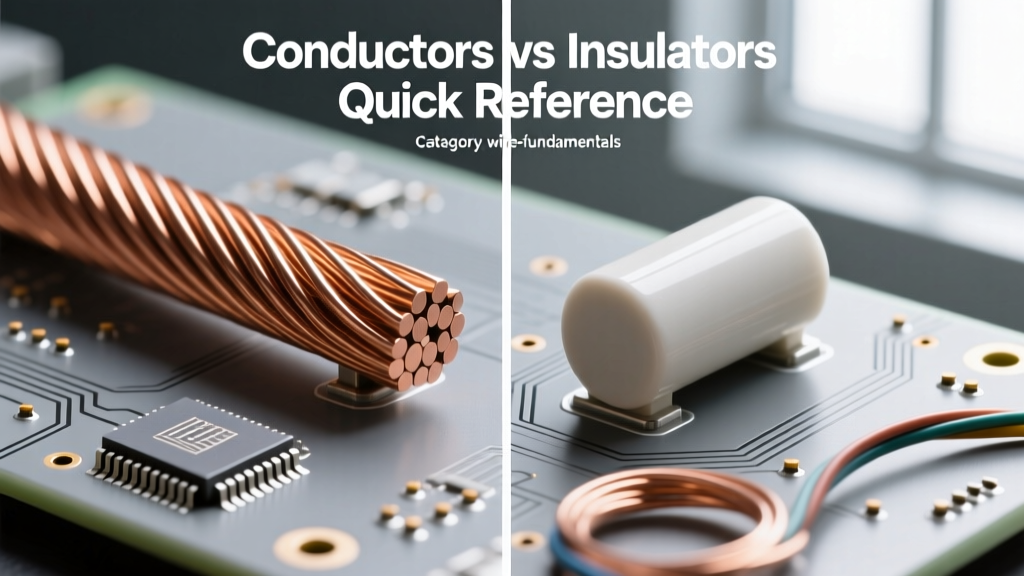
A conductor is a material that permits the free flow of electrical current due to its abundance of free electrons in the conduction band. Copper and aluminum are the industry standards. An insulator, conversely, has tightly bound valence electrons that resist electron flow, creating a barrier that confines the current to its intended path. Materials like cross-linked polyethylene (XLPE) and polyvinyl chloride (PVC) serve this role. In a safety context, the conductor is the hazard source, and the insulator is the primary engineered safeguard.
Conductor Hazards: When the Path of Least Resistance Fails
While conductors are designed to carry current, they are not perfect. They possess inherent resistance, which generates heat proportional to the square of the current (I²R losses). Safety failures involving conductors rarely stem from the material itself failing to conduct, but rather from improper sizing, termination, or material selection.
Thermal Overload and Conductor Sizing
Undersizing a conductor for a specific load is one of the most common safety violations in electrical wiring. According to the NFPA 70 National Electrical Code (NEC), conductors must be sized based on ampacity tables that account for ambient temperature and bundling. If a 14 AWG copper wire (rated for 15 amps) is subjected to a continuous 20-amp load, the conductor's temperature will exceed the thermal rating of its surrounding insulation. This leads to insulation melting, exposed live conductors, and inevitable short circuits.
The Aluminum Oxidation and Creep Hazard
Aluminum is a highly effective conductor, but it introduces unique safety hazards compared to copper. Aluminum oxidizes rapidly when exposed to air, forming aluminum oxide—a highly resistive insulator. If this oxide layer is not managed with antioxidant compounds and proper wire brushing, the connection point will overheat. Furthermore, aluminum is subject to "creep" or cold flow under pressure. If terminations are not torqued to the manufacturer's exact specifications using a calibrated torque screwdriver, the connection will loosen over time due to thermal cycling, resulting in high-resistance faults and arc fires.
Insulator Vulnerabilities: The Breakdown of the Invisible Shield
Insulators are not infinitely resistive. Every insulating material has a dielectric strength, measured in kilovolts per millimeter (kV/mm), which dictates the maximum electric field it can withstand before it fails. When asking what is an insulator and a conductor in high-voltage or high-heat scenarios, the line between the two can literally vanish.
Dielectric Breakdown and Arc Tracking
Dielectric breakdown occurs when the voltage applied to an insulator exceeds its structural limits, tearing electrons from their atomic bonds and turning the insulator into a temporary conductor. In standard 120V/240V residential wiring, this is rare under normal conditions. However, transient voltage surges (like lightning strikes) or long-term degradation can compromise the dielectric barrier. Once a microscopic puncture occurs, carbon tracking can begin. Carbon is conductive; as the arc burns the insulation, it leaves a carbonized path that eventually bridges the gap between conductors, leading to a phase-to-phase or phase-to-ground fault.
Thermal Degradation of Common Wire Jackets
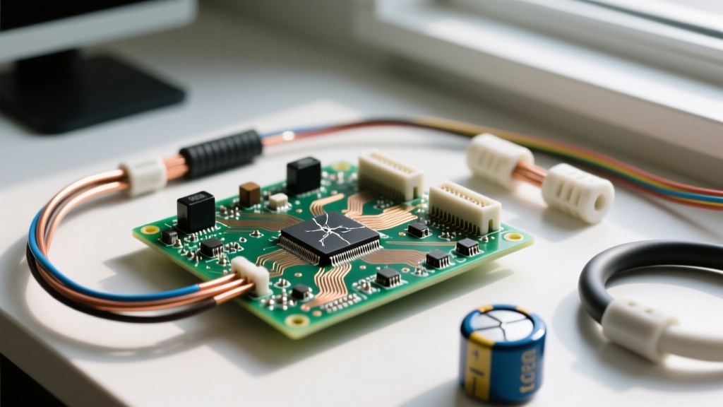
Heat is the silent killer of electrical insulation. Standard THHN (Thermoplastic High Heat-resistant Nylon-coated) wire utilizes a PVC base. While rated for 90°C in dry locations, the NEC generally restricts termination ampacities to the 75°C column due to the thermal limits of standard breakers and lugs. Continuous exposure to temperatures above these thresholds causes the plasticizers in the PVC to leach out, making the insulation brittle. Once brittle, normal mechanical vibration or thermal expansion/contraction will cause the insulation to crack, exposing the live conductor.
Safety Directive: Never rely solely on the 90°C rating of modern wire insulation for sizing overcurrent protection. Always adhere to OSHA Electrical Safety Standards and NEC 110.14(C), which mandates that termination temperature limits dictate the maximum allowable ampacity.
Material Safety Profile: Conductors vs. Insulators
To maintain a safe electrical system, technicians must understand the specific failure modes of the materials they are working with. The following table outlines the critical safety parameters for common wiring materials.
| Material | Role | Critical Safety Parameter | Common Failure Mode | Safety Mitigation Strategy |
|---|---|---|---|---|
| Copper (Cu) | Conductor | High conductivity, thermal expansion | Overheating due to undersizing | Strict adherence to NEC ampacity tables; voltage drop calculations. |
| Aluminum (Al) | Conductor | Oxidation, cold creep | High-resistance termination fires | Use antioxidant paste; torque lugs to exact manufacturer specs. |
| PVC (THHN) | Insulator | Dielectric strength, 90°C max rating | Brittle cracking from thermal aging | Derate for ambient heat; avoid sharp bending radii during pulls. |
| XLPE (XHHW-2) | Insulator | Superior thermal/chemical resistance | Moisture ingress if jacket is cut | Inspect jacket before pulling; use in wet/damp locations. |
Field Diagnostics: Testing Insulation and Conductor Integrity
Visual inspection is insufficient for verifying the safety of conductors and insulators. Hidden degradation within conduit or behind panels requires specialized diagnostic equipment. As detailed in manufacturer wire specifications, testing ensures the materials are performing within their engineered tolerances.
Megohmmeter (Megger) Testing
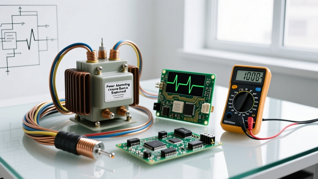
A standard digital multimeter applies only a few volts to test continuity, which cannot reveal microscopic weaknesses in an insulator. A megohmmeter applies high DC voltage (typically 500V or 1000V for low-voltage systems) to measure insulation resistance in megohms. A safe, healthy insulation system should read in the hundreds or thousands of megohms. A reading below 1 megohm indicates severe dielectric degradation, moisture ingress, or carbon tracking, requiring immediate wire replacement before energizing the circuit.
Infrared (IR) Thermography
Because conductors generate heat when resistance increases, infrared cameras are vital for safety inspections. By scanning electrical panels under load, technicians can identify "hot spots" at termination points. A lug that is 10°C to 20°C hotter than adjacent phases indicates a loose connection, oxidation (in aluminum), or a failing conductor strand. Catching these thermal anomalies prevents catastrophic arc flash incidents.
Micro-Ohmmeter Testing for Conductors
To ensure the conductor itself is not damaged, a micro-ohmmeter measures the resistance of busbars, cables, and splices in micro-ohms. If a conductor has been mechanically stretched, kinked, or suffered internal strand breakage during installation, its resistance will spike. This localized resistance acts as an unintended heating element, slowly destroying the surrounding insulator from the inside out.
Conclusion: Respecting the Material Limits
Ultimately, understanding what is an insulator and a conductor is about respecting their physical and thermal boundaries. Conductors must be sized to manage heat, and terminations must be mechanically secure to prevent resistance. Insulators must be protected from UV, chemical, and thermal degradation to maintain their dielectric strength. By combining rigorous adherence to the NEC with advanced field diagnostics like megger testing and IR thermography, electrical professionals can ensure that the vital boundary between energy flow and human safety remains unbroken.