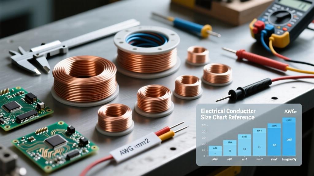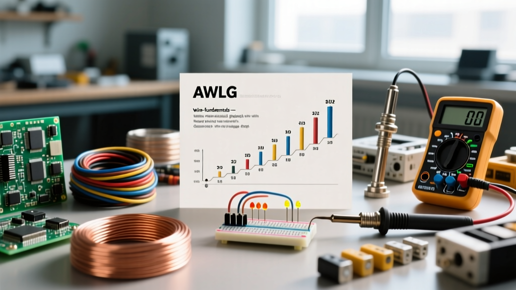

Decoding the Wire Size Range: A Practical Comparison
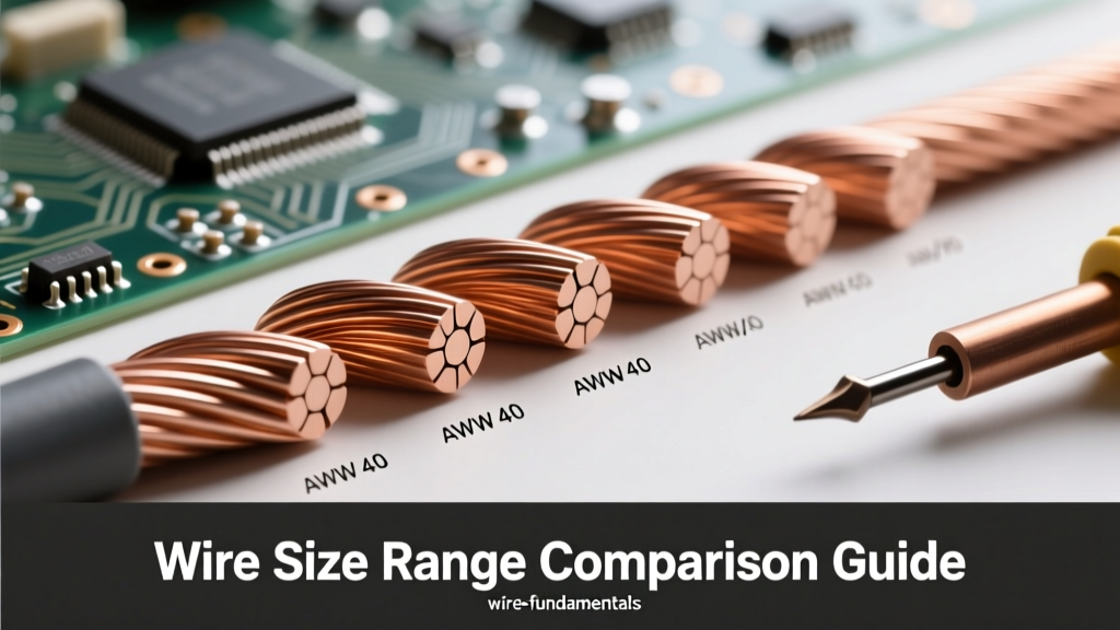
Whether you are designing a low-voltage PCB, wiring a residential kitchen, or sizing feeders for a 400-amp commercial subpanel, understanding the complete wire size range is the foundation of electrical safety and efficiency. The American Wire Gauge (AWG) system and its metric (mm²) and circular mil (kcmil) counterparts dictate not only how much current a conductor can safely carry, but also how it behaves under thermal stress, voltage drop constraints, and high-frequency skin effects.
In this comparison guide, we break down the vast wire size range into four distinct operational categories. We will compare ampacity limits, material behaviors, and real-world code restrictions governed by the National Electrical Code (NFPA 70). By the end of this guide, you will have a robust decision-making framework for selecting the exact conductor required for your specific application.
The Logarithmic Anatomy of Wire Gauges
Before comparing specific applications, it is crucial to understand the mathematical logic governing the AWG system. Unlike linear measurements, the wire size range in AWG is logarithmic.
- The Rule of 3: For every 3-gauge decrease in AWG (e.g., from 12 AWG to 9 AWG), the cross-sectional area and current-carrying capacity roughly double.
- The Rule of 10: For every 10-gauge decrease (e.g., from 14 AWG to 4 AWG), the cross-sectional area increases by a factor of 10, and the resistance drops to one-tenth.
- Zero and Aughts: Once you pass 1 AWG, the scale moves to 1/0 (one-aught), 2/0, 3/0, and 4/0. Beyond 4/0, the industry abandons AWG and switches to thousands of circular mils (kcmil or MCM).
Master Data Table: Core Wire Size Range Metrics
The following table provides a rapid comparison of the most common conductors in the standard wire size range, referencing 75°C copper ampacities based on Cerrowire and NEC Table 310.15(B)(16) standards.
| AWG / kcmil | Area (mm²) | Diameter (in) | Max Ampacity (75°C Cu) | Typical Application Tier |
|---|---|---|---|---|
| 14 AWG | 2.08 | 0.064 | 20A (15A OCPD limit) | Residential Lighting |
| 12 AWG | 3.31 | 0.081 | 25A (20A OCPD limit) | Receptacles, Small Appliances |
| 10 AWG | 5.26 | 0.102 | 35A (30A OCPD limit) | Dryers, Water Heaters |
| 6 AWG | 13.30 | 0.162 | 65A | EV Chargers, Subpanels |
| 2 AWG | 33.62 | 0.258 | 115A | 100A Residential Services |
| 4/0 AWG | 107.20 | 0.460 | 230A | 200A Residential Services |
| 350 kcmil | 177.30 | 0.592 | 310A | Commercial Feeders |
Comparative Analysis: Four Distinct Wire Size Ranges
To effectively specify conductors, electrical professionals divide the wire size range into four functional tiers. The physics, code requirements, and installation techniques shift dramatically across these tiers.
Tier 1: Micro and Electronics (AWG 30 to AWG 18)
In the smallest wire size range, mechanical fragility and high-frequency signal integrity take precedence over raw ampacity. Conductors in this range are almost exclusively stranded (e.g., 7-strand or 19-strand bunch tinned copper) to survive vibration and flexing.
Key Considerations: At high frequencies, the 'skin effect' forces current to travel only on the outer perimeter of the wire. Therefore, a 20 AWG stranded wire with a higher surface-area-to-volume ratio may outperform a solid 20 AWG wire in RF applications. Furthermore, insulation types like PTFE (Teflon) or MIL-W-16878E rated PVC are mandatory here to prevent melting during micro-soldering operations.
Tier 2: Residential Branch Circuits (AWG 14 to AWG 10)
This is the most heavily regulated wire size range in the NEC due to its proximity to end-users and high fire risk. While the physical copper in a 14 AWG wire can technically handle 20 amps at 60°C, NEC 240.4(D) imposes strict Overcurrent Protective Device (OCPD) limits: 15A for 14 AWG, 20A for 12 AWG, and 30A for 10 AWG.
Voltage Drop Reality: While code allows 14 AWG on a 15-amp breaker, running a 14 AWG circuit 150 feet to a distant receptacle will result in a voltage drop exceeding the recommended 3%. In these scenarios, upsizing to 12 AWG or 10 AWG is required not for ampacity, but to maintain voltage stability for sensitive electronics.
Tier 3: Commercial Feeders and Subpanels (AWG 8 to 4/0)
Once you cross into AWG 8 and larger, the wire size range transitions from simple Romex (NM-B) cable to individual conductors pulled through raceways (THHN/THWN-2 or XHHW-2). Here, terminal temperature ratings become the primary bottleneck.
Even though THHN wire is rated for 90°C in the insulation column of NEC Table 310.15(B)(16), almost all breakers and lugs rated under 100A are only tested and certified for 75°C terminations. Therefore, you must use the 75°C column for ampacity calculations. For example, a 4 AWG copper THHN wire has a 90°C ampacity of 95A, but you can only use it on an 85A breaker because its 75°C ampacity is limited to 85A.
Tier 4: Utility and Heavy Industrial (250 kcmil to 1000 kcmil)
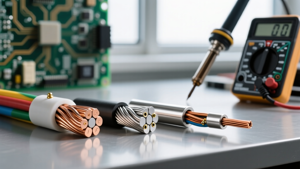
At the top end of the wire size range, solid conductors are physically impossible to bend. These cables are heavily stranded, often compacted or compressed to reduce the overall diameter and fit into standard conduit.
Parallel Runs: According to standard engineering practices and NEC 310.10(G), once you require conductors larger than 1000 kcmil, it becomes more practical to run multiple parallel sets of smaller wires (e.g., two sets of 500 kcmil) rather than a single massive cable. Parallel runs require exact length matching to ensure equal impedance and prevent one conductor from carrying a disproportionate share of the load.
Material Showdown: Copper vs. Aluminum Across the Spectrum
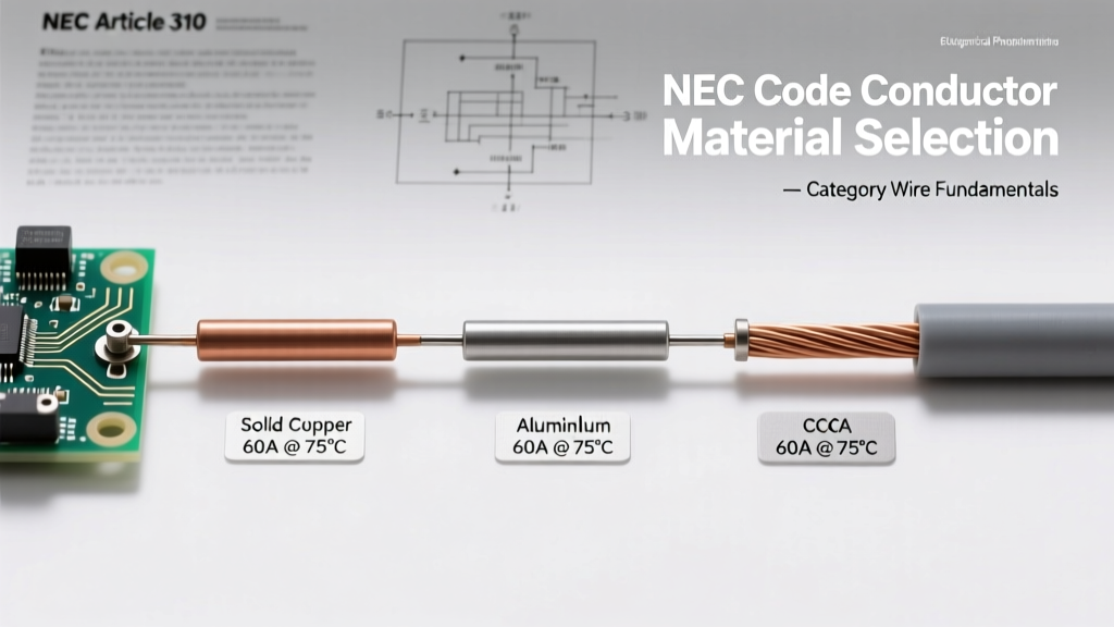
The choice between copper and aluminum radically alters the effective wire size range you must select. Aluminum has roughly 61% of the conductivity of copper by volume. Consequently, an aluminum conductor must be sized approximately two AWG steps larger than its copper equivalent to carry the same current.
Expert Insight: Never use aluminum wire in the Tier 1 or Tier 2 ranges. Aluminum's high coefficient of thermal expansion and susceptibility to galvanic corrosion make it dangerous for small, high-vibration, or frequently manipulated branch circuit connections. Aluminum is strictly a Tier 3 and Tier 4 material, ideal for heavy feeders where weight and material cost savings outweigh the installation complexities.
When terminating the upper wire size range in aluminum, you must apply an anti-oxidant compound (like Noalox) to prevent aluminum oxide—a highly resistive insulator—from forming at the lug interface. Furthermore, aluminum requires strict adherence to torque specifications using a calibrated torque screwdriver or wrench to prevent 'cold flow' or 'creep' over time, which leads to loose connections and catastrophic arc faults.
Real-World Troubleshooting: Mismatched Wire Size Range Failures
Misunderstanding the boundaries of the wire size range leads to specific, diagnosable failure modes in the field.
Failure Mode 1: The Shared Neutral Harmonic Overload
In commercial settings (Tier 3), electricians often use a multi-wire branch circuit or a 4-wire feeder to serve non-linear loads like LED drivers, VFDs, and server racks. While the phase wires might be perfectly sized within their wire size range for the fundamental 60Hz current, triplen harmonics (3rd, 9th, 15th) do not cancel out on the neutral. Instead, they add up. It is entirely possible for the neutral conductor to carry 150% of the phase current. Solution: In heavy harmonic environments, the neutral wire must be upsized by at least one or two gauge steps, or a dedicated neutral must be pulled for each phase.
Failure Mode 2: The 90°C Termination Trap
A common mistake among junior engineers is sizing a feeder based on the 90°C ampacity column of THHN wire to save money. For instance, using a 3 AWG THHN copper wire (100A at 90°C) to feed a 100A subpanel. However, because the panel's main lug is only rated for 75°C, the wire is effectively limited to 85A. Under continuous load, the breaker terminals will overheat, discolor the lug, and eventually degrade the insulation jacket, leading to a ground fault. Always terminate based on the weakest link's temperature rating.
Final Verdict on Wire Sizing
Mastering the wire size range requires looking beyond simple ampacity charts. It demands a holistic comparison of thermal limits, voltage drop over distance, termination hardware ratings, and the specific harmonic profile of the connected loads. By segmenting your project into the appropriate tier and strictly adhering to NEC termination rules, you ensure a system that is not only code-compliant but engineered for decades of reliable service.