
The Fundamental Question: Is Iron a Conductor or Insulator?
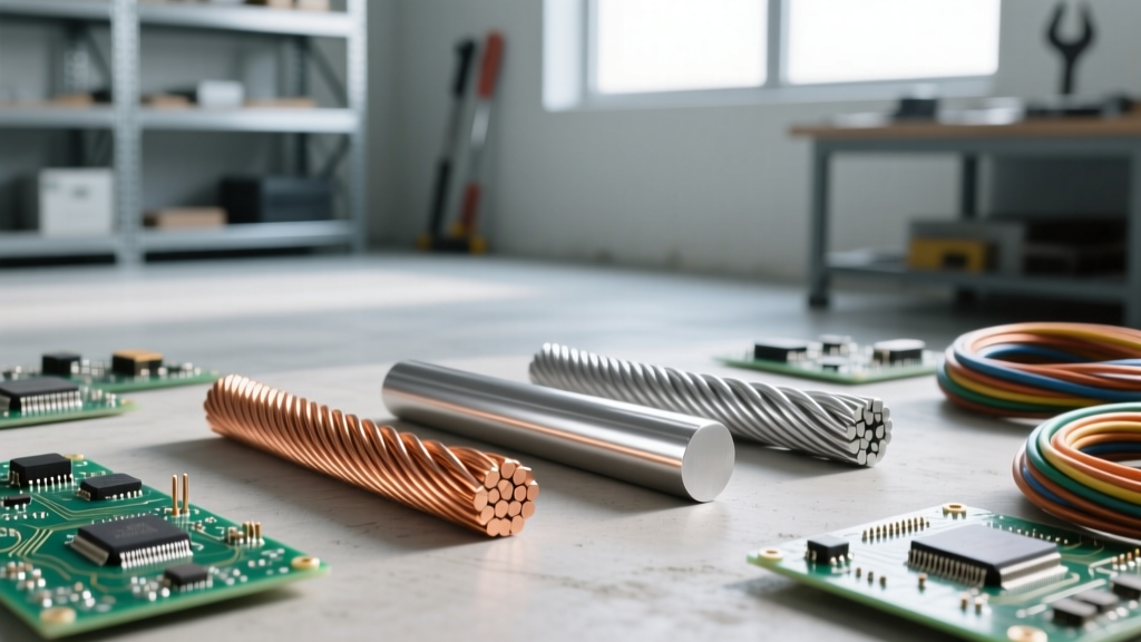
When evaluating materials for DIY electronics, custom battery packs, or workshop wiring, a common fundamental question arises: is iron a conductor or insulator? The definitive answer is that iron is a conductor. However, in the realm of electrical engineering and wire sizing, it is classified as a high-resistivity conductor. While it easily allows the flow of electrical charge compared to true insulators like rubber, glass, or PTFE, its atomic structure creates significant friction for electron flow compared to standard conductors like copper or aluminum.
As a calculation tutorial, this guide moves beyond the basic yes-or-no answer. We will mathematically prove iron's conductive properties, calculate its exact resistance using both metric and circular mil formulas, and analyze the severe voltage drop and thermal failure modes that dictate why iron is almost never used for modern branch circuit wiring.
Atomic Structure and Electron Scattering in Iron
To understand iron's electrical behavior, we must look at its crystalline structure. Iron is a transition metal with a body-centered cubic (BCC) lattice structure at room temperature. In metallic bonding, the outer valence electrons detach from their parent atoms, forming a "sea of delocalized electrons" that carry current when a voltage potential is applied.
However, the BCC lattice of iron is less tightly packed than the face-centered cubic (FCC) lattice of copper. This structural difference, combined with iron's magnetic domains and higher atomic mass, causes frequent electron scattering. Every time an electron collides with the vibrating iron lattice (phonons) or magnetic irregularities, kinetic energy is lost as heat. This phenomenon is quantified as electrical resistivity ($\rho$).
- Resistivity of Annealed Copper: $\approx 1.68 \times 10^{-8} \, \Omega\cdot\text{m}$ at 20°C
- Resistivity of Pure Iron: $\approx 9.71 \times 10^{-8} \, \Omega\cdot\text{m}$ at 20°C
As documented by Georgia State University HyperPhysics, iron is approximately 5.8 times more resistive than copper. This single data point is the foundation for all subsequent wire sizing calculations.
Step-by-Step Metric Resistance Calculation
Let us calculate the exact DC resistance of a hypothetical iron wire and compare it to a copper wire of the exact same dimensions. We will use a standard 12 AWG wire, which is common in DIY 20-amp circuits.
1. Define the Parameters
- Wire Gauge: 12 AWG
- Cross-Sectional Area (A): $3.31 \times 10^{-6} \, \text{m}^2$ (or $3.31 \, \text{mm}^2$)
- Length (L): 100 feet ($30.48 \, \text{meters}$)
- Temperature: 20°C (Standard reference)
2. Apply the Resistance Formula
The fundamental formula for resistance is $R = \rho \times (L / A)$.
For Copper:
$R_{cu} = (1.68 \times 10^{-8} \, \Omega\cdot\text{m}) \times (30.48 \, \text{m} / 3.31 \times 10^{-6} \, \text{m}^2)$
$R_{cu} = 0.154 \, \Omega$
For Iron:
$R_{fe} = (9.71 \times 10^{-8} \, \Omega\cdot\text{m}) \times (30.48 \, \text{m} / 3.31 \times 10^{-6} \, \text{m}^2)$
$R_{fe} = 0.894 \, \Omega$
Over a mere 100 feet, the iron wire exhibits nearly six times the resistance of the copper wire. In a complete circuit (which requires a 200-foot round trip for hot and neutral/ground), the total iron wire resistance approaches $1.78 \, \Omega$.
The Circular Mil Method for Iron Wiring
In North American wire sizing, electricians rely on Circular Mils (CM) and the specific resistance constant ($K$). The formula is $R = (K \times L) / CM$.
According to standard resistivity tables referenced by The Engineering Toolbox, the $K$ value for copper is roughly 10.4 to 12.9 (depending on temperature and stranding). For iron, the $K$ value is approximately 59.
Calculation using Circular Mils (12 AWG = 6,530 CM, L = 100 ft):
$R_{fe} = (59 \times 100) / 6530 = 0.903 \, \Omega$.
This closely matches our metric calculation, validating the math across different unit systems.
Comparative Data Table: 12 AWG Conductors over 100 Feet
| Material | Resistivity ($\Omega\cdot\text{m}$) | K-Factor (Approx) | Resistance (100 ft) | Voltage Drop @ 15A | Power Dissipation (Heat) |
|---|---|---|---|---|---|
| Copper | $1.68 \times 10^{-8}$ | 10.4 | $0.154 \, \Omega$ | 2.31 Volts | 34.6 Watts |
| Aluminum | $2.65 \times 10^{-8}$ | 17.0 | $0.260 \, \Omega$ | 3.90 Volts | 58.5 Watts |
| Iron | $9.71 \times 10^{-8}$ | 59.0 | $0.894 \, \Omega$ | 13.41 Volts | 201.1 Watts |
Note: Voltage drop and power dissipation are calculated for a single 100-foot conductor carrying a continuous 15-Amp DC load ($V = I \times R$ and $P = I^2 \times R$).
Voltage Drop and Thermal Failure Modes
The data table above reveals the fatal flaw of using iron as a primary circuit conductor. If you push 15 Amps through 100 feet of 12 AWG iron wire, you lose over 13 volts. In a 120V AC system, this drops the voltage at the load to roughly 93V (accounting for the round-trip neutral wire), which will cause motors to stall, electronics to malfunction, and incandescent lights to dim severely.
The $I^2R$ Heating Problem
More dangerously, that missing electrical energy does not just disappear; it converts into thermal energy. The iron wire will dissipate over 200 Watts of heat along its 100-foot length. While spread out, this might not immediately melt the wire, it will rapidly degrade standard PVC or THHN insulation, which is typically rated for 60°C to 90°C. Iron wiring in a conduit will easily exceed these thermal limits under continuous load, creating a severe fire hazard.
The Iron Oxide Insulator Trap
Perhaps the most critical information gain for DIYers is understanding iron's chemical failure mode. When copper oxidizes, it forms copper oxide, which is a semiconductor and still allows some current flow at termination points. When iron oxidizes, it forms Iron(III) oxide ($Fe_2O_3$), commonly known as rust. Iron oxide is a highly effective electrical insulator.
Expert Warning: If you attempt to terminate an iron wire under a standard brass or copper screw terminal, galvanic corrosion will accelerate the oxidation process. The resulting layer of iron oxide will act as an insulator at the connection point, causing massive contact resistance, localized arcing, and eventual thermal runaway at the receptacle or breaker lug.
Practical Applications: Where Iron Wiring is Actually Used
Given these severe electrical and thermal penalties, why do we still discuss iron in electrical fundamentals? Because iron and its alloys are engineered for specific scenarios where its high resistivity or mechanical strength is an advantage.
- Grounding Electrodes: Copper-clad steel (an iron alloy core) ground rods are standard in NEC-compliant installations. The steel provides the mechanical rigidity needed to be driven into rocky soil, while the copper cladding provides the conductive path and corrosion resistance. Pure iron ground rods exist but are prone to rapid subterranean corrosion.
- Heating Elements: Alloys of iron, chromium, and nickel (Nichrome) leverage iron's high resistivity to intentionally generate heat. By carefully calculating the wire gauge and length, engineers design toaster elements and industrial kilns that glow red-hot without melting.
- High-Voltage Transmission Cores: Overhead power lines often use ACSR (Aluminum Conductor Steel Reinforced) cable. The outer strands are highly conductive aluminum, while the inner core is steel (iron-based) to bear the immense mechanical tension of spanning hundreds of feet between towers.
Summary and Sizing Verdict
To conclusively answer the prompt: iron is unequivocally a conductor, but its high atomic resistivity makes it entirely unsuitable for standard power distribution, DIY branch circuits, or low-voltage electronics. When performing wire sizing calculations, substituting iron for copper requires increasing the cross-sectional area by a factor of nearly 6 to maintain the same voltage drop and thermal safety margins—a physically and economically impractical solution. Always rely on copper or aluminum for conductive pathways, and reserve iron and steel for structural support, grounding electrodes, and intentional resistive heating applications.
For further reading on standard material conductivity and safety margins, consult the IEEE Xplore Digital Library and local electrical codes regarding approved conductor materials.